搜索
bottom↓
回复: 40

JLH1969 Power amp

[复制链接]

出0入0汤圆

发表于 2009-5-3 18:38:36 | 显示全部楼层 |阅读模式
just thought some of you may be interested in sim files for JLH1969.

the first is JLH1969B, using bipolar output devices. it runs in Class A only.

C6/R10 is optional.


(原文件名:jlh1969b.PNG)

阿莫论坛20周年了!感谢大家的支持与爱护!!

一只鸟敢站在脆弱的枝条上歇脚,它依仗的不是枝条不会断,而是自己有翅膀,会飞。

出0入0汤圆

 楼主| 发表于 2009-5-3 18:39:29 | 显示全部楼层
here is the Proteus sim file.

点击此处下载 ourdev_441719.rar(文件大小:15K) (原文件名:JLH1969B.rar)

出0入0汤圆

 楼主| 发表于 2009-5-3 18:41:58 | 显示全部楼层
the 2nd uses MOSFETs as output devices. It works in Class A or Class B, depending on the idle current.

点击此处下载 ourdev_441720.rar(文件大小:16K) (原文件名:JLH1969M.rar)

(原文件名:jlh1969m.PNG)

出0入0汤圆

 楼主| 发表于 2009-5-3 18:42:27 | 显示全部楼层
in the JLH1969M schematic, C6 is optional.

出0入0汤圆

 楼主| 发表于 2009-5-3 18:43:00 | 显示全部楼层
in both designs, R9 adjusts idle current: small R9 brings higher idle current.

出0入0汤圆

发表于 2009-5-3 22:18:21 | 显示全部楼层
^_^非常经典的1969 ,这两年正在DIY热潮很高。  是一款非常值得DIY的分立功放

出0入0汤圆

发表于 2009-5-31 23:14:37 | 显示全部楼层
大侠的贴,要顶。
很想听millwood0上堂课,这个电路的工作原理,还有MOSFET的电路工作在AB类时静态功耗有多大,输出10W时消耗掉的功耗有多大,声音如何?

出0入0汤圆

 楼主| 发表于 2009-6-1 21:40:56 | 显示全部楼层
it is simple:

1) r1/c1: input decoupling. R1 also helps with stability at high frequencies.
2) r2/r3/r4/c4: sets up Q1's DC bias. You can use a trimmer in place of R2/R3 and to change output DC.
3) Q1 is the input amplification stage, with R5 as its load. the feedback is applied to Q1's emitter so this is a current feedback design. This is why the JLH1969 has an open loop frequency response over 20khz (vs. usually < 10hz for a VFB opamp).
4) R6/R7 sets up the gain.
5) Q2 is the phase splitter: it outputs two signals, one from its emitter and another from its collector, that are 180 degrees apart.
6) R8/R9/C2 form a bootstrap network. C2 has to be an electrolytic capacitor - so that the gain of the bootstrap network goes DOWN as C2 becomes less of an ideal capacitor (>80khz typically).
7) Q3/Q4 are output devices. R11/R12 are the gate stoppers to keep the output mosfets stable.

"还有MOSFET的电路工作在AB类时静态功耗有多大,"

I typically idle my amps so that the voltage drop on the Re resistors (r13/r14) is 25mv. that means about 100ma idle current.

so the dissipation on the output devices is about 16v*0.1amp=2w, per device, assuming rail voltage of 32v.

"输出10W时消耗掉的功耗有多大,"

the efficiency there is about 45 - 50%. so they dissipate about 10w.

"声音如何?"

this amp is  widely built and I think it is one of the best sounding amps I have ever heard and I have heard a lot of them.

出0入0汤圆

发表于 2009-6-1 22:08:26 | 显示全部楼层
想知道为什么叫JLH1969?

出0入0汤圆

发表于 2009-6-1 23:31:02 | 显示全部楼层
Thanks millwood0

仍然有些问题理解得不是很全面。
1、整个电路的直流偏置除了Q1的比较好理解以外,其他的管子直流偏置好像有点“错综复杂“相互影响。为什么需要C4?
2、增益的计算:(是否如下)
对于交流小信号Q1的基极vi = vb1 = ve1 = vo*(R7/(R6+R7))
                                     Av = 1+R6/R7 = 1+1000/110 = 10
这里将C5考虑为交流短路,但实际应该考虑容抗,如果考虑容抗,那么对不同频率信号的放大倍数就不同。
我理解R6、R7是将输出电压的一部分反馈回Q2的发射极,应该是电压反馈,怎么说是电流反馈呢?
3、去掉C6后,频率特性在200K左右的产生尖锋,加上C6后就消除了该效应。C6是否对高频起到了电压并联负反馈?
4、三极管的电路只能工作在A类,MOSFET就可以工作在AB类,为什么?

谢谢。可能我对模拟电路不敏感,本来以为对教科书上的电路基本都搞懂了,但电路换一个花样就又看不明白了。

出0入0汤圆

发表于 2009-6-1 23:42:27 | 显示全部楼层
回8楼,据说是JLH在1969年的一个论文上发表的这个电路,所以就被称为了JLH1969.

出0入0汤圆

 楼主| 发表于 2009-6-2 02:01:17 | 显示全部楼层
"1、整个电路的直流偏置除了Q1的比较好理解以外,其他的管子直流偏置好像有点“错综复杂“相互影响。为什么需要C4? "

C4 maintains the DC voltage from the R2/R3 divider.

"2、增益的计算:(是否如下)
对于交流小信号Q1的基极vi = vb1 = ve1 = vo*(R7/(R6+R7))  
                                     Av = 1+R6/R7 = 1+1000/110 = 10
这里将C5考虑为交流短路,但实际应该考虑容抗,如果考虑容抗,那么对不同频率信号的放大倍数就不同。 "

yes. That's why C5 is very large.

"我理解R6、R7是将输出电压的一部分反馈回Q2的发射极,应该是电压反馈,怎么说是电流反馈呢? "

it is current feedback because the "impedance" looking into Q1's emitter is very low (< 50ohm).

"3、去掉C6后,频率特性在200K左右的产生尖锋,加上C6后就消除了该效应。C6是否对高频起到了电压并联负反馈? "

C6 is the typical miller cap. It is NOT needed in real life since the gain from the bootstrap goes down at higher frequency (as C2 becomes less ideal, which the sim doesn't factor in).

"4、三极管的电路只能工作在A类,MOSFET就可以工作在AB类,为什么? "

because the output stage is current coupled with BJT and voltage coupled with MOSFET.

"回8楼,据说是JLH在1969年的一个论文上发表的这个电路,所以就被称为了JLH1969."

it was initially published in the april 1969 issue of wireless world. I started calling it JLH1969 to distinguish it from the 1996 revision.

出0入0汤圆

 楼主| 发表于 2009-6-2 02:03:04 | 显示全部楼层
JLH is the initials of the author's name: John Linsley Hood.

出0入0汤圆

发表于 2009-6-2 17:17:52 | 显示全部楼层

(原文件名:dianlu.JPG)


(原文件名:tran.JPG)
相同的参数,为什么我的得不到AB类的结果呢?图中绿线是R11的电流,红线是R12的电流。
应该是调节R8、R9的值来调节工作点?

出0入0汤圆

发表于 2009-6-2 17:26:27 | 显示全部楼层
这是我的仿真文件
点击此处下载 ourdev_450128.rar(文件大小:84K) (原文件名:JLH1969M.rar)

出0入0汤圆

 楼主| 发表于 2009-6-2 18:58:02 | 显示全部楼层
"相同的参数,为什么我的得不到AB类的结果呢?图中绿线是R11的电流,红线是R12的电流。
应该是调节R8、R9的值来调节工作点?"

because yours is working in Class A (idling at .9amp), with both devices conducting during the entire 360 degrees.

Increasing R8 will put the amp into Class B.

出0入0汤圆

发表于 2009-6-3 14:46:03 | 显示全部楼层
谢谢millwood0,我通过调节R8,或者R14,可以得到不同的类别A、AB
昨晚在万能板上搭了一个,音质听上去还行。不过我没有32V的电源,只做了个20V的版本,声音有点小(5x的增益)。不知是不是音量小的原因,感觉有点闷。

出0入0汤圆

 楼主| 发表于 2009-6-3 18:47:33 | 显示全部楼层
you shouldn't change R14: it determines the idle current for Q2. changing R8 is the way to go.

as to sound quality, it should be very good: I have some really good amps (a Parasound, two HK AVRs, a Signature 7.1) and the little JLH beats them all in sound quality.

出0入0汤圆

发表于 2009-6-11 09:09:07 | 显示全部楼层
LZ的第一个电路中,R9改成恒流源是不是更合理一些?

目前的电路看上去总有一些怪怪的感觉,——直流偏置点说不清楚。

按照LZ在7楼的说法,静态电流是100mA,因此,Q2的发射极电压在0.8V左右,发射极电流大概8mA,集电极电流也应该是8mA,如此一来,仅靠Q2的集电极电流是无法保证R8、R9提供Q3的基极偏置的,所以,Q3上应该有很大的基极电流才行,——Q3处于饱和状态?

如果把R9换成恒流源,相对而言就简单多了。

出0入0汤圆

 楼主| 发表于 2009-6-11 20:31:14 | 显示全部楼层
"LZ的第一个电路中,R9改成恒流源是不是更合理一些? "

it depends on what you want to do. The bootstrap network (R8/R9/C2) IS a constant current source, a passive one that is. The beauty of it is that at higher frequencies, C2 becomes less of a capacitor, and the network loses its gain. This is why you don't need the miller cap if the bootstrap network is used.

JLH in his 1996 update (JLH1996) did replace the bootstrap network with a CCS, and as a result had to use a miller cap to keep the amp stable. the general consensus is that JLH1996 does NOT sound as good as JLH1969.

"目前的电路看上去总有一些怪怪的感觉,——直流偏置点说不清楚。

按照LZ在7楼的说法,静态电流是100mA,因此,Q2的发射极电压在0.8V左右,发射极电流大概8mA,集电极电流也应该是8mA,如此一来,仅靠Q2的集电极电流是无法保证R8、R9提供Q3的基极偏置的,所以,Q3上应该有很大的基极电流才行,——Q3处于饱和状态? "

the DC bias calculation is just too simple.

take the BJT  version for example. R2/R3 determines Q1's base voltage, thus Q1's emitter voltage. that in turn determines Q3's emitter voltage and its base voltage (roughly 1/2 Vcc + 2* Vbe). That determines the idle current going through Q2 =(Vcc-1/2 Vcc-2*Vbe)/(R8+R9). That current is shared between Q3 and Q4's base equally.

so assume Vcc=32v. Q1's base is at 1/2 Vcc=16v. Q1's emitter is at 16.7v. and Q3's base is at 16.7v+0.7v=17.5v. so the current going through R8/R9=(32v-17.5v)/(110+110)=15/220=65ma. sim shows 60ma.

the current going through Q2 is half of that.

you can work out that for the mosfet version similarly.

"如果把R9换成恒流源,相对而言就简单多了。 "

yes and no.

出0入0汤圆

发表于 2009-6-12 05:36:57 | 显示全部楼层
谢谢millwood0 的说明。

还有几个疑问:

1。按楼上的说法,Q3、Q4基极电流应该都是30mA左右,Vce都是10V以上,如此一来,静态条件下的Q3/Q4发射极电流都应该在2A以上,与模拟结果存在比较大的差异,难道还有其它因素在起作用?而且,这个静态电流应该与电流放大倍数密切相关,是通过R9限制的么?感觉不是这么回事。

2。C2/R9的存在好像在一定程度上还充当了前馈功能,其前馈量与R9/R10取值有关,关于这个问题,有什么特别的说明么?

3。从电路结构来看,Q3好像是充当了Q4的恒流源负载,因为Q3、Q4使用了相同型号的管子,才需要C2、R8自举回路,如果用互补型号三极管,应该就没有如此复杂,而且还更容易控制静态电流,在这里,是不是也还有其它考虑?

出0入0汤圆

 楼主| 发表于 2009-6-12 18:57:35 | 显示全部楼层
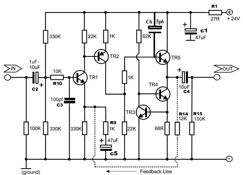
"1。按楼上的说法,Q3、Q4基极电流应该都是30mA左右,Vce都是10V以上,如此一来,静态条件下的Q3/Q4发射极电流都应该在2A以上,与模拟结果存在比较大的差异,难道还有其它因素在起作用?而且,这个静态电流应该与电流放大倍数密切相关,是通过R9限制的么?感觉不是这么回事。 "

how much idle current you get in Q3/Q4 depends on their hFE, once R9 is determined.

"2。C2/R9的存在好像在一定程度上还充当了前馈功能,其前馈量与R9/R10取值有关,关于这个问题,有什么特别的说明么? "

C2/R9 do nothing. C2/R9/R8 form a passive constant current source to increase the phase splitter's open loop gain.

there is no feedforward here.

"3。从电路结构来看,Q3好像是充当了Q4的恒流源负载,因为Q3、Q4使用了相同型号的管子,才需要C2、R8自举回路,如果用互补型号三极管,应该就没有如此复杂,而且还更容易控制静态电流,在这里,是不是也还有其它考虑? "

Q3 is an emitter follower to the signal output from the bootstrap network (C2/R9/R8). the use of the bootstrap network has nothing to do with if Q3/Q4 are of the same transistors. you can get rid of C2 and the amp will continue to work - you will need to use a miller cap to keep it stable, through.

the amp will work if Q4 is configured into a constant current source, or a simple resistor. Actually, that's how this topology is used for preamp.

you can use a complementary pair here, but you will have to temperature compensate them so they are thermally stable. the BJT version of the JLH1969 is inherently thermal stable. so the use of a complementary pair will complicate the design, rather than simplify it.

出0入0汤圆

 楼主| 发表于 2009-6-12 23:23:12 | 显示全部楼层
here is an example of how you can make a preamp or headphone amp out of the jlh1969. We basically replaced the lower output device with a resistor. the amp works just as well, with lower efficiency, but also slightly lower distortion.

you can use a CCS in place of the resistor (R58) for better efficiency and higher slew rate.


(原文件名:jlh1969 preamp headphone amp.PNG)

出0入0汤圆

 楼主| 发表于 2009-6-12 23:23:40 | 显示全部楼层
what about using a complementary pair as output device?

it is also doable.

B1 is your Vbe multiplier, and you can run the amp in Class A or Class B by adjusting B1.


(原文件名:jlh1969 complementary OPS.PNG)

出0入0汤圆

 楼主| 发表于 2009-6-13 05:19:15 | 显示全部楼层
here is a true preamp - it cannot be used to drive a (low-impedance) headphone.

its gain is 3x, determined by 1+ r93/R97.

distortion is primarily 2nd order harmonics (300uv vs. 3v, or 0.01%). 3rd order harmonics is about 75uv (0.003%). not bad.

if you want to use it as a headphone amp, you will need to use a beefier Q16 (bd139 or mje150xx), and downside  R96 to match.

enjoy.


(原文件名:jlh1969 preamp.PNG)

出0入0汤圆

 楼主| 发表于 2009-6-13 18:18:27 | 显示全部楼层
and here is the schematic of a world famous preamp. Compare it with the one I posted in #24, :).


(原文件名:Naim Preamp Gain_board_schem.jpg)

出0入0汤圆

发表于 2009-6-15 08:12:03 | 显示全部楼层
磨坊可不可以把1996的电路也发上来看看啊?谢谢了!

出0入0汤圆

发表于 2009-8-3 08:58:21 | 显示全部楼层
1969音质很好,我想把他改成耳放,静态电流调整到多少最好?

出0入0汤圆

 楼主| 发表于 2009-8-3 19:51:35 | 显示全部楼层
idle current depends on a lot of factors.

if you are using a low-impedance headphone (<64ohm), you need no more th an 1v Vp to drive the headphone. That means 100ma peak current will do. I would idle a 1969B at 300ma and a 1969M at 100ma.

出0入0汤圆

发表于 2009-8-4 15:22:01 | 显示全部楼层
ths millwood.
是否工作电压可以降低,你认为作为耳放,供电电压大概多少合适,我使用的是24V。考虑发热量和功耗,我准备改成12V
,是否可行?

出0入0汤圆

 楼主| 发表于 2009-8-5 06:01:52 | 显示全部楼层
it depends on your headphone. for most low-impedance headphones, 1v Vp will be sufficient. That means you need about 6v (2Vpp + 4v for saturation) rail for 1969B, and about 12v (2Vpp + 10v fr saturation) rail for 1969M.

出0入0汤圆

发表于 2010-7-11 21:00:08 | 显示全部楼层
记号,学一点。

出0入0汤圆

发表于 2010-10-31 23:24:05 | 显示全部楼层
记号 学习了。

出0入0汤圆

发表于 2010-11-9 21:18:46 | 显示全部楼层
有没有清楚一点的电路。最近想做

出0入0汤圆

发表于 2010-11-9 22:29:04 | 显示全部楼层
mark

出0入0汤圆

发表于 2010-11-10 09:51:14 | 显示全部楼层
我也作了个MOS版的,用40V供电,声音非常好.
参考了millwood的图,元件值有改动.偏流为200mA.

出0入0汤圆

发表于 2011-8-28 14:00:12 | 显示全部楼层
马克   做之

出0入0汤圆

发表于 2013-1-13 14:07:25 | 显示全部楼层
甲类功放 令人羡慕的东东。

出0入399汤圆

发表于 2013-7-21 23:15:45 | 显示全部楼层
"The bootstrap network (R8/R9/C2) IS a constant current source"

can you tell me the current value and what is the function of C2?bootstrap?why need bootstrap?

出0入399汤圆

发表于 2013-7-25 07:21:29 | 显示全部楼层
问楼主两个疑问:
1,上面电路的开环增益如何计算?
2,下面图片对于I的计算如何求得,就以15欧负载为例,希望楼主说一下:

本帖子中包含更多资源

您需要 登录 才可以下载或查看,没有帐号?注册

x

出0入399汤圆

发表于 2013-7-25 08:03:02 | 显示全部楼层
millwood0 发表于 2009-6-1 21:40
it is simple:

1) r1/c1: input decoupling. R1 also helps with stability at high frequencies.

还有几个问题:
1,楼主说R1是为了高频稳定,不知道什么原因呢?
2,还有楼主判断是电流反馈还是电压反馈貌似是从反馈终端的阻抗进行判断,貌似跟教材的从反馈起始端的方法不一样?
3,Q3,Q4谁是谁的有源负载,貌似都不是,因为两者电流都在不断变化,都不是恒流源,不知道说的对不对?

谢谢前辈的解答!
回帖提示: 反政府言论将被立即封锁ID 在按“提交”前,请自问一下:我这样表达会给举报吗,会给自己惹麻烦吗? 另外:尽量不要使用Mark、顶等没有意义的回复。不得大量使用大字体和彩色字。【本论坛不允许直接上传手机拍摄图片,浪费大家下载带宽和论坛服务器空间,请压缩后(图片小于1兆)才上传。压缩方法可以在微信里面发给自己(不要勾选“原图),然后下载,就能得到压缩后的图片】。另外,手机版只能上传图片,要上传附件需要切换到电脑版(不需要使用电脑,手机上切换到电脑版就行,页面底部)。
您需要登录后才可以回帖 登录 | 注册

本版积分规则

手机版|Archiver|amobbs.com 阿莫电子技术论坛 ( 粤ICP备2022115958号, 版权所有:东莞阿莫电子贸易商行 创办于2004年 (公安交互式论坛备案:44190002001997 ) )

GMT+8, 2024-5-20 11:20

© Since 2004 www.amobbs.com, 原www.ourdev.cn, 原www.ouravr.com

快速回复 返回顶部 返回列表