|
|
FFT结果的物理意义 : 可以参考本论坛链接:
http://www.ourdev.cn/bbs/bbs_content.jsp?bbs_sn=3944963&bbs_page_no=1&search_mode=1&search_text=FFT&bbs_id=9999
开发板采用ICETEK-F2812-A
FFT计算采用TI的FFT程序,信号发生器产生正弦波信号,输入ACD0,AD采样率为3KHz,
注意:2812输入的电压:0-3V,信号发生器的正弦波信号应有一个整的offset。
2812的主程序:
实际的FFT运算程序:
#include "DSP281x_Device.h" // DSP281x Headerfile Include File
#include "DSP281x_Examples.h" // DSP281x Examples Include File
/* for test fft */
#include "fft.h"
// Prototype statements for functions found within this file.
interrupt void adc_isr(void);
// Global variables used in this example:
Uint16 LoopCount;
Uint16 ConversionCount;
Uint16 Voltage1[1024];
Uint16 Voltage2[1024];
#define N 1024 //FFT Length
#pragma DATA_SECTION(ipcb, "FFTipcb");
#pragma DATA_SECTION(mag,"FFTmag");
RFFT32 fft=RFFT32_1024P_DEFAULTS;
long ipcb[N+2]; //In place computation buffer
long mag[N/2+1]; //Magnitude buffer
//const long win[N/2]=HAMMING128; //Window coefficient array
RFFT32_ACQ acq=FFTRACQ_DEFAULTS; //Instance the module
main()
{
int i;
InitSysCtrl();//初始化cpu
DINT;//关中断
InitPieCtrl();//初始化pie寄存器
/* Initialize acquisition module */
acq.buffptr=ipcb;
acq.tempptr=ipcb;
acq.size=N;
acq.count=N;
acq.acqflag=1;
/* Initialize FFT module */
fft.ipcbptr=ipcb;
fft.magptr=mag;
fft.init(&fft);
IER = 0x0000;//禁止所有的中断
IFR = 0x0000;
InitPieVectTable();//初始化pie中断向量表
// Interrupts that are used in this example are re-mapped to
// ISR functions found within this file.
EALLOW; // This is needed to write to EALLOW protected register
PieVectTable.ADCINT = &adc_isr;
EDIS; // This is needed to disable write to EALLOW protected registers
AdcRegs.ADCTRL1.bit.RESET = 1; // Reset the ADC module
asm(" RPT #10 || NOP"); // Must wait 12-cycles (worst-case) for ADC reset to take effect
AdcRegs.ADCTRL3.all = 0x00C8; // first power-up ref and bandgap circuits
AdcRegs.ADCTRL3.bit.ADCBGRFDN = 0x3; // Power up bandgap/reference circuitry
AdcRegs.ADCTRL3.bit.ADCPWDN = 1; // Power up rest of ADC
// Enable ADCINT in PIE
PieCtrlRegs.PIEIER1.bit.INTx6 = 1;
IER |= M_INT1; // Enable CPU Interrupt 1
EINT; // Enable Global interrupt INTM
ERTM; // Enable Global realtime interrupt DBGM
LoopCount = 0;
ConversionCount = 1;
// Configure ADC
AdcRegs.ADCMAXCONV.all = 0x0001; // Setup 2 conv's on SEQ1
AdcRegs.ADCCHSELSEQ1.bit.CONV00 = 0x0; // Setup ADCINA3 as 1st SEQ1 conv.
AdcRegs.ADCCHSELSEQ1.bit.CONV01 = 0x1; // Setup ADCINA2 as 2nd SEQ1 conv.
AdcRegs.ADCTRL2.bit.EVA_SOC_SEQ1 = 1; // Enable EVASOC to start SEQ1
AdcRegs.ADCTRL2.bit.INT_ENA_SEQ1 = 1; // Enable SEQ1 interrupt (every EOS)
// Configure EVA
// Assumes EVA Clock is already enabled in InitSysCtrl();
EvaRegs.T1CMPR = 0x0080; // Setup T1 compare value
EvaRegs.T1PR = 0x61a8; // Setup period register
EvaRegs.GPTCONA.bit.T1TOADC = 1; // Enable EVASOC in EVA
EvaRegs.T1CON.all = 0x1042; // Enable timer 1 compare (upcount mode)
// Wait for ADC interrupt
while(1)
{
//LoopCount++;
if (acq.acqflag==0) // If the samples are acquired
{
DINT;
//RFFT32_brev(ipcb,ipcb,N);
//RFFT32_brev(ipcb,ipcb,N); // Input samples in Real Part
fft.calc(&fft);
fft.split(&fft);
fft.mag(&fft);
for(i=0;i<N;i++)
{
mag=sqrt(mag);
}
acq.acqflag=1; // Enable the next acquisition
EINT;
}
}
}
interrupt void adc_isr(void)
{
Voltage1[ConversionCount] = AdcRegs.ADCRESULT0>>4;
acq.input=((unsigned long)Voltage1[ConversionCount])<<16;
acq.update(&acq);
// ipcb[ConversionCount]=((unsigned long)Voltage1[ConversionCount])<<16;
Voltage2[ConversionCount] = AdcRegs.ADCRESULT1 >>4;
// If 40 conversions have been logged, start over
if(ConversionCount == 1023)
{
ConversionCount = 0;
// acq.acqflag=0;
}
else ConversionCount++;
// Reinitialize for next ADC sequence
AdcRegs.ADCTRL2.bit.RST_SEQ1 = 1; // Reset SEQ1
AdcRegs.ADCST.bit.INT_SEQ1_CLR = 1; // Clear INT SEQ1 bit
PieCtrlRegs.PIEACK.all = PIEACK_GROUP1; // Acknowledge interrupt to PIE
return;
}
/*
//###########################################################################
//
// FILE: F2812_EzDSP_RAM_lnk.cmd
//
// TITLE: Linker Command File For F2812 eZdsp examples that run out of RAM
// This linker file assumes the user is booting up in Jump to H0 mode
//
//###########################################################################
//
// Ver | dd mmm yyyy | Who | Description of changes
// =====|=============|======|===============================================
// 1.00| 11 Sep 2003 | L.H. | Changes since previous version (v.58 Alpha)
// | | | Added BEGIN section to the start of H0
// | | | Removed .bss, .const and .sysmem
// | | | These are for a small memory model. All examples
// | | | use the large model.
// | | | Added .esysmem section
// | | | Changed ramfuncs section to load and run from RAM
// | | | (previously this was type DSECT)
// | | | Moved peripheral register files to DSP28_Headers_BIOS.cmd
// | | | and DSP28_Headers_nonBIOS.cmd
// | | | Added CSM_RSVD memory section in FLASHA - this region
// | | | should be programmed with all 0x0000 when using the CSM
// -----|-------------|------|-----------------------------------------------
//###########################################################################
*/
/* ======================================================
// For Code Composer Studio V2.2 and later
// ---------------------------------------
// In addition to this memory linker command file,
// add the header linker command file directly to the project.
// The header linker command file is required to link the
// peripheral structures to the proper locations within
// the memory map.
//
// The header linker files are found in <base>\DSP281x_Headers\cmd
//
// For BIOS applications add: DSP281x_Headers_nonBIOS.cmd
// For nonBIOS applications add: DSP281x_Headers_nonBIOS.cmd
========================================================= */
/* ======================================================
// For Code Composer Studio prior to V2.2
// --------------------------------------
// 1) Use one of the following -l statements to include the
// header linker command file in the project. The header linker
// file is required to link the peripheral structures to the proper
// locations within the memory map */
/* Uncomment this line to include file only for non-BIOS applications */
/* -l DSP281x_Headers_nonBIOS.cmd */
/* Uncomment this line to include file only for BIOS applications */
/* -l DSP281x_Headers_BIOS.cmd */
/* 2) In your project add the path to <base>\DSP281x_headers\cmd to the
library search path under project->build options, linker tab,
library search path (-i).
/*========================================================= */
-l rts2800.lib
-w
-stack 400h
-heap 100
MEMORY
{
PAGE 0 :
/* For this example, H0 is split between PAGE 0 and PAGE 1 */
/* BEGIN is used for the "boot to HO" bootloader mode */
/* RESET is loaded with the reset vector only if */
/* the boot is from XINTF Zone 7. Otherwise reset vector */
/* is fetched from boot ROM. See .reset section below */
//RAMM0 : origin = 0x000000, length = 0x000400
//RAMM0 : origin = 0x3f6000, length = 0x001000
BEGIN : origin = 0x3F8000, length = 0x000002
/*BEGIN : origin = 0x3F7FF6, length = 0x000002*/
PRAMH0 : origin = 0x3f8002, length = 0x000FFE
PRAMH1 : origin = 0x80000, length = 0x0FFFF /* 64K external RAM */
RESET : origin = 0x3FFFC0, length = 0x000002 /* part of boot ROM (MP/MCn=0) or XINTF zone 7 (MP/MCn=1) */
VECTORS : origin = 0x3FFFC2, length = 0x00003E /* part of boot ROM (MP/MCn=0) or XINTF zone 7 (MP/MCn=1) */
PAGE 1 :
/* For this example, H0 is split between PAGE 0 and PAGE 1 */
L0L1RAM (RW) : origin = 0x008000, length = 0x2000
RAMM1 : origin = 0x000400, length = 0x000400
DRAMH0 : origin = 0x3f9000, length = 0x001000
}
SECTIONS
{
/* Setup for "boot to H0" mode:
The codestart section (found in DSP28_CodeStartBranch.asm)
re-directs execution to the start of user code.
Place this section at the start of H0 */
codestart : > BEGIN, PAGE = 0
ramfuncs : > PRAMH0 PAGE = 0
.text : > PRAMH0, PAGE = 0
.cinit : > PRAMH0, PAGE = 0
.pinit : > PRAMH0, PAGE = 0
.switch : > PRAMH0, PAGE = 0
.reset : > RESET, PAGE = 0, TYPE = DSECT /* not used, */
FFTtf > PRAMH0, PAGE = 0
DLOG > PRAMH0, PAGE = 0
FFTipcb ALIGN(2048) : { } > PRAMH1 PAGE 0
FFTmag > PRAMH1 PAGE 0
SINTBL : > L0L1RAM, PAGE = 1
.stack : > RAMM1, PAGE = 1
.ebss : > DRAMH0, PAGE = 1
.econst : > DRAMH0, PAGE = 1
.esysmem : > DRAMH0, PAGE = 1
.const : > DRAMH0, PAGE = 1
.sysmem : > DRAMH0, PAGE = 1
.cio : > DRAMH0, PAGE = 1
}
FFTipcb, FFTmag 的配置必须注意。
aca.updata
可以把ipcb 输入数据与输出数据定义为同一数据,来节省内存
在开始FFT计算时需要
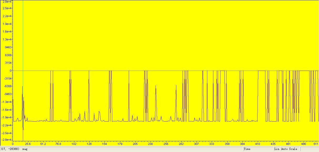
DINT 屏蔽A/D采集中断,结束FFT计算后EINT,以保证
再没有DINT A/D采集时,的截图:A/D采集不连续,

(原文件名:FFT.jpg)
输入信号正弦Vpp 500mV,直流偏置500mV。此时输入的信号:0.5+0.5sin(2*pi*50*t)V
此时,ADC0输入的波形:2812ADC 为12位
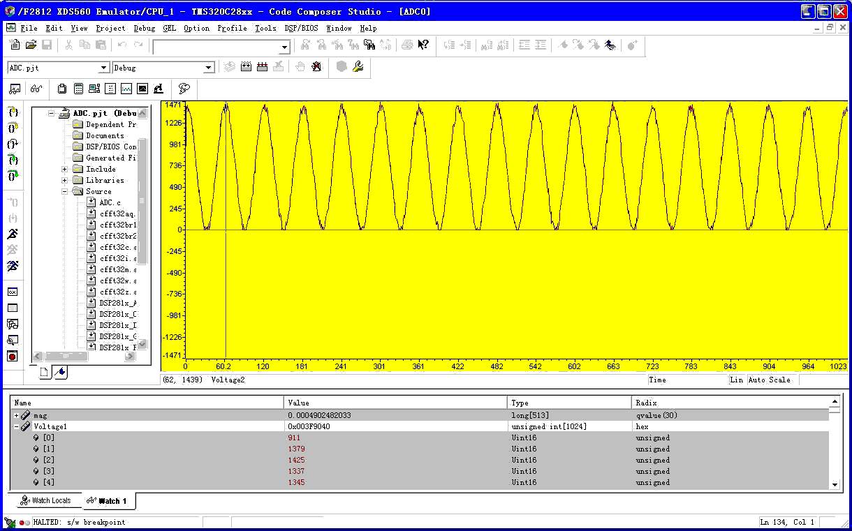
(原文件名:FFT.jpg)
FFT的图形:对ADC直接FFT变换:数据演算:
FFT的magtude为357578 变化为电压值 357578/(n/2)/4095*3=0.5115V ,n=1024

(原文件名:FFT.jpg)
调用2812的FFT子程序进行变换: 数据验算 mag 格式为Q30格式,mag=sqrt(0.00726813)*3*2=0.51152V
f=17*3000/1024=49.8Hz
Ti的FFT程序已经考虑到定点数的溢出问题,在每级的缩放系数为2,所以不用再除以N了,
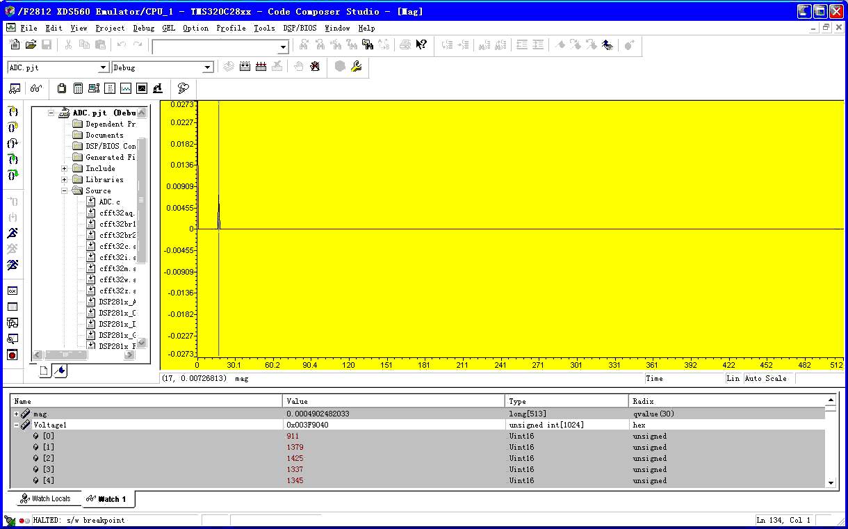
(原文件名:FFT.jpg)
最终的计算结果合实际值有一点差别。 |
阿莫论坛20周年了!感谢大家的支持与爱护!!
月入3000的是反美的。收入3万是亲美的。收入30万是移民美国的。收入300万是取得绿卡后回国,教唆那些3000来反美的!
|


 发表于 2010-7-1 17:06:43
 楼主
楼主