|
|
昨天偶然发现一个简单胆机耳放,一个ECC88(可用6N11替换)加NJM4556跟随输出,适合入门练练手。
找到作者的主页,有详细的制作与调试讲解,简单翻译了一下放上来供大家参考。
第一次翻译东西,如有谬误敬请指正。
原文地址:http://www.fa-schmidt.de/YAHA/index.htm
制作完成图:
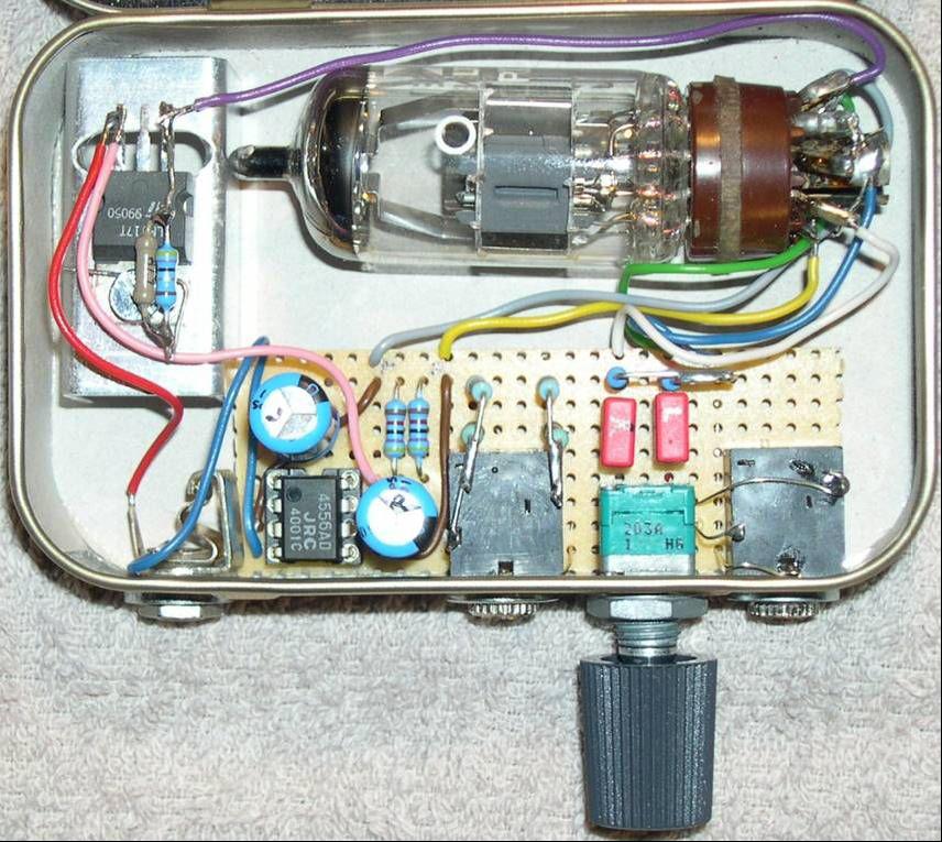
(原文件名:YAHA.JPG)
电路图:
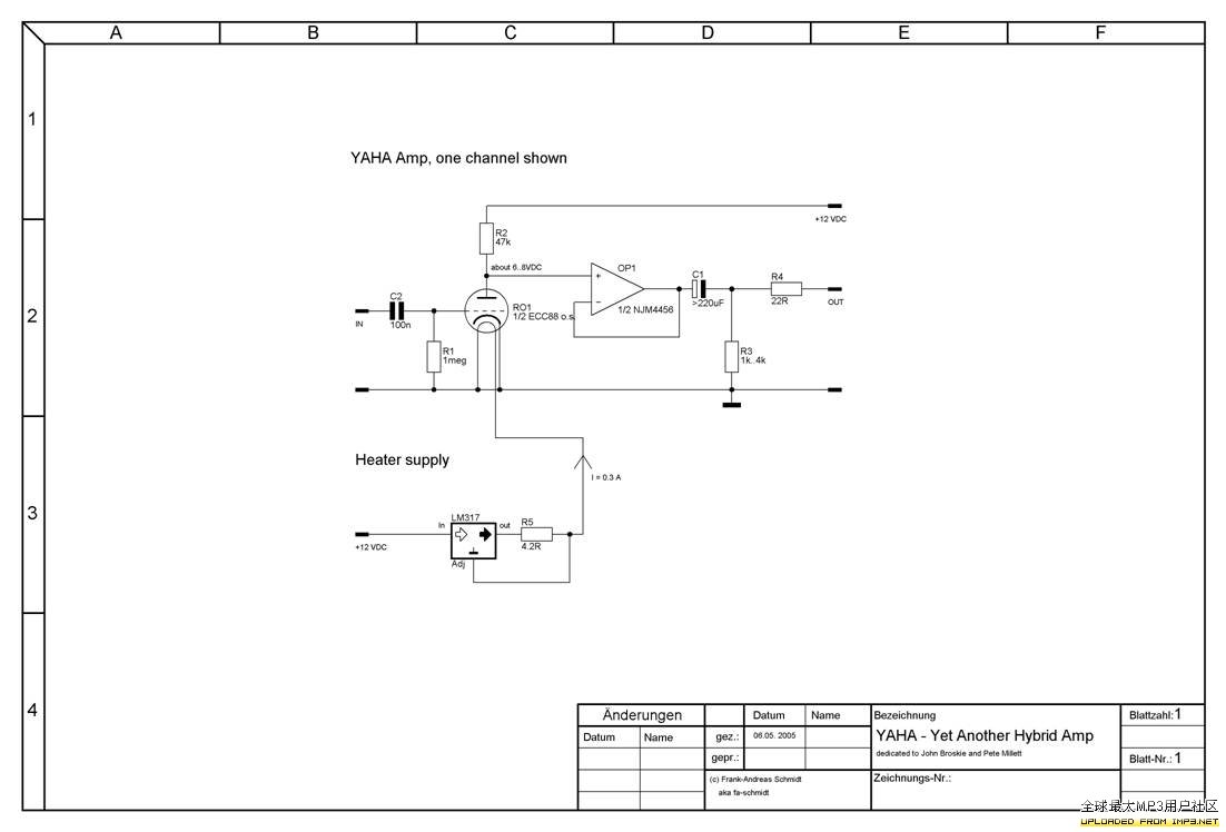
(原文件名:ourdev_492533.jpg)
Basically, this is a grounded cathode voltage amp followed by an opamp buffer.
简单的说,这是一个带运放缓冲的阴极接地电压放大器
For full understanding ignore the opamp stage and look at the tubed voltage amp.
为了充分的理解这个电子管电压放大器,请忽略后面运放部分。
Just cut (in memory) the wire between the tube and the opamp (+) input.
在脑海里想像着切断电子管与运放正向输入脚的引线。
The triode is fixed-biased by the grid-charge current that flows through the 1meg resistor.
电子管通过1M电阻提供的栅极电流处于固定偏置状态。
To explain this:
下面来解释下这点:
The hot cathode always emitts some electrons that have enough energy to fly up to the grid.
发热状态的阴极不停发射电子到栅极上。
The grid resistor closes the current path between grid and cathode so that the grid discharges across the resistor and following Ohm′s law built
栅极电阻连接在栅极和阴极的电流环路上,根据欧姆定律,栅极通过这个电阻进行放电。
This way of biasing works for many small signal tubes like 6DJ8, ECC88, 6922 ,6N11 but also for 12AT7, 12AX7 etc..
这样的偏置状态不但可以驱动6DJ8,ECC88,6922,6N11等小信号电子管,而且支持12AT7,12AX7等管子。
It works for pentodes as well, like DAF96, 1T4.
它还能驱动五极电子管,如DAF96,1T4等。
It won’t work for power tubes like 2A3 or so because the bias voltage is in the range of -0.3..-0.8VDC only.
但是不能驱动功率管,如2A3,因为它的偏置电压范围只有-0.3...-0.8VDC。
Choosing the value of the grid resistor:
栅极电阻的选择:
It′s written in the books. It is that value named “max. grid resistor” and often is combined with the type of bias: Automatic or fixed. Choose the value for “fixed”.
数据手册都有规定栅极电阻的阻值,通常称为“最大栅极电阻”,并且是结合偏置类型(自动或固定)来说明的,我们选择固定。
Here I have to correct myself:
现在,我要对这个阻值进行修正。
If the book says “fixed bias” this is for an external negative voltage to be applied to the grid.
如果手册说明是“固定偏置”,这说明偏置是通过在栅极上施加负压实现的。
If the book says “automatic bias” this is for the bias acquired by a cathode resistor.
如果手册说明是“自动偏置”,这说明偏置是通过阴极电阻来实现的。
Most books don’t say anything about “grid-leakage bias” !!! If there is a value, use it.
很多手册没有提到“栅漏偏置”,如果有提到的话,就用这个值。
If not: Use the value for automatic bias and multiply it by 10.
如果没有,就使用自动偏置的值并乘上10倍。
In my circuit the R1 value should be up to 10 megOhm .
在我的电路的,R1的值应该是10M欧。
The circuit works ok for R1 = 1megOhm but one can be sure that there is a small amount of grid current flowing.
这样电路在R1=1M欧的情况下也可以工作,但可以肯定是,栅极会有少量的电流流过。
Choosing a plate resistor:
选择屏极(阳极)电阻:
Normally you would take the value off the data book, too. But in this case it is not possible because the plate voltage is so low that no curves exist for most of the tubes.
通常你会从数据手册上获得这个数据,但是在现在这种情况下是不可能的,因为阳极电压太低了,大多数电子管数据手册不会提供如此低的阳极电压-电阻曲线图。
Here is a procedure how to get a value without curve-tracing.
下面是不通过曲线跟踪法来确定阳极电阻的方法
The plate resistor value is chosen that it will consume 4..6 V from the 12 V DC power. I recommed that this resistor is adjustable if you use any other tube than the 6DJ8 series or want to use other supply voltages.
阳极电阻的取值以其上的分压为4至6V为宜(在供电电压为12V的情况下)。如果你不是使用6DJ8或者使用不同的供电电压时,我建议你采用一个可调电阻来做阳极电阻。
Always adjust the plate resistor to consume 1/2 to 1/3 of the supply voltage.
通常调节这个阻值使其上面的分压为1/2至1/3的供电电压。
If you try pentodes the plate resistor may consume up to 2/3 of the supply voltage.
如果你想使用五极真空管的话,那阳极电阻上面的分压要达到2/3的供电电压。
Start with a high value, up to 200kOhm, and adjust to lower while continously measuring the voltage between plate and B+ until it fits.
先将电阻调整至高阻值,如200K欧,然后慢慢的往下调整,直到其上的分压达到要求。
Now take the adjustable resistor off the circuit and measure the resistance. You now may choose the standard value nearest to the result of the measurement.
现在,可以把可调电阻取下来并测量其阻值,然后选择和其最接近的标准阻值来使用。
An amplified input signal can now be seen at the opamp (+) input if we “repair” the wire we cut above.
现在可以把我们前面假想的已经切断的信号线重新连入运放的正向端了。
The opamp in the prototype is an NJM4456 dual opamp. It is able to feed as much as 70mA into a 150 Ohm load.
电路原型中使用的运放是NJM4456双运放,在负载为150欧时它可以输出高达70mA的电流。
The NJM is not as “hot” as modern opamps with enormous high gain-bandwidth products. So it is not very likely that you will have problems with noise or oszillation.
这个运放不像现在很热门的产品,没有高增益带宽,所以不会让你遇到诸如噪音或震荡等问题。
You may also try other opamps like NE5532 or OPA2134 or so. Make sure that they are “unity gain stable”. That means they will work flawlessly at a gain of 1.
你也可以尝试其它的运放,如NE5532、OPA2134等等,但要确定它们具有稳定的单位增益。这表示他们可以在放大倍数为1的状态下完美地工作。
That´s the configuration we need. We wire the output to the negative input and feed the signal into the positive input. From the DC point of view this input sits at about 1/2 of the supply voltage, according how exactly you have chosen the plate resistor. In steady-state the output of the opamp follows the input (with a gain of 1 here) and therefore sits at 1/2 of the supply voltage, too.
下面是我们需要达到的配置状态:将运放输出端连接至反向输入端,并在正向端输入信号。从直流工作点的角度来看,输入端的电压大约是供电电压的1/2.这取决于你调整阳极电阻的精度。在稳态下,运放的输出电压跟随输入电压,并且具有1/2供电电压的静态工作点。
Side note:
旁注:
You could use a standard buffer like the BUF634, too. It is more expensive, provides even more current and you need two of those.
你可以使用标准的缓冲器,如BUF634。它的价格更贵,可以提供更多的电流,并且同时需要两片。
The result is the same: The output follows the input and sits at 1/2 B+.
但是结果是一样的:输出电压跟随输入电压,工作点为1/2工作电压。
Ok. Here is another correction:
好,下面是其它的一些调整:
It was reported that the BUF634 would be outside a feedback loop and therefore is nearly incontrollable. It may work or not…
据报告称,BUF634容易出现超调不可控的状况
A better way is to put a MOSFET source follower as a buffer behind the opamp.
一个更好的办法是在跟随器后面增加MOS管扩流。
We do not like to feed the headphones with DC, so we need to go with an output cap.
我们不希望对耳机提供直流电压,所以需要添加一个输出电容。
Warning: Never go without output cap, otherwise your headphones (and probably your ears) will be ruined immediately.
注意:一定不能省略输出电容,否则你的耳机(甚至是你的听力)将会很快受损。
You may use an electrolytic of 220uF for cans above 32 Ohms, like the PortaPro or SportaPro. You should use 470uF for lo-Z headphones.
对于阻抗高于32欧姆的耳机,如高斯的PortaPro或SportaPro耳机.你可以使用220uF的电解电容。对于低阻抗耳机(小于32欧姆),需要使用470uF的输出电容。
Some people put a small film cap in parallel to the electrolytic to have better high frequency response.
有些人在电解电容上并联一个小容量的薄膜电容以获得更好的高频响应。
Important: Watch the polarity of the cap. The + side of the cap goes toward the opamp output !
重要提示:注意电容的极性,正极接运放的输出端。
Eessential are the two resistors after the cap.
这个电路的精髓是电容后面的两个电阻。
The bleeder resistor:
泄流电阻:
This one, to ground, will allow the cap to charge at power on.
这个电阻,接到地线上,用于上电时对电容进行充电。
This helps to minimize the POP when you connect the headphones.
这可以减少插上耳机时听到“噗”声。
Side note:
旁注:
You should connect / disconnect the headphones always if the amp is up and running.
你应该在放大器处于工作状态时连接或断开耳机。
You won´t notice POPs and this helps to preserve the sound qualities of the headphones.
你将不会注意到“噗”声,这有助于提高音质。
The bleeder resistor should be about 10 times higher than the value of the headphone impedance plus the output resistor value.
泄流电阻的阻值应该高于耳机阻抗与输出电阻值之和的10倍。
The output resistor:
输出电阻:
The output resistor is chosen between 22 and 150 Ohm depending on which final gain the amp should have.
输出电阻的阻值应该在22至150欧姆之间,这取决于放大器最后应有的增益。
The output resistor forms a a voltage divider together with the headphone impedance.
输出电阻和耳机的阻抗组成一个分压器。
As a rule of thumb choose the low value for high-Z headphones (>=250 Ohm) and the high value for lo-Z headphones (32 Ohm).
作为一个经验法则,对于高阻抗的耳机应选择低的输出电阻阻值,对于低阻抗的耳机应该选择高的输出电阻阻值
Changing the value of the output resistor has _some_ effect on the sound and the stability of the opamp stage.
改变这个阻值会对听感和运放工作稳定性有一定的影响。
The NJM likes load impedances of 100 Ohm and higher best.
NJM4456运放的负载要高于100欧姆,并且越高越好。
Feeding the heater:
驱动电子管的灯丝:
This is done by an LM317T voltage regulator wired as constant current source.
这部分由LM317组成的恒流源来完成。
You only need one for two channels because the tube is a double triode, having two triode systems inside.
你只需要一个管子即可满足双通道的需求,因为它里面是双三极管结构。
Check the tube data: The 6DJ8 is fired with 300mA constant current or 6.3VDC constant voltage.
查看管子的数据手册:6DJ8灯丝工作方式为300mA恒流或6.3V恒压。
We choose constant current. This is easy to achieve with the LM317 and an additional resistor.
我们选择恒流供电方式,这样只有一片LM317和一个电阻即可。
The current flowing is given by the formula: I = 1.25 V / R, or solved for R:
电流大小通过这个公式来计算:I = 1.25 V / R,反过来计算R:
R = 1.25V / I = 1.25V / 0.3 A = 4.2 Ohm |
阿莫论坛20周年了!感谢大家的支持与爱护!!
月入3000的是反美的。收入3万是亲美的。收入30万是移民美国的。收入300万是取得绿卡后回国,教唆那些3000来反美的!
|


 发表于 2010-10-15 16:24:57