|
|
发送时间: 2008-06-30 21:46:12
收件人:
抄送:
主题: (ATTicket:331858) Support Form: avr493 application note can not run
(Please keep the subject when replying to this mail)
Hello,
First, I advice to do not use the old CD you could have received in the past. The data on the CD are very confusing, a lot of sources are not up to date .
For ATAVRMC100 boards, all sources with documentation are available on the Web :
AVR492 for BLDC motor in sensor based mode.
AVR493 for BLDC motor in sensorless mode.
The AVR493 requires an additional hardware for sensorless.
The AVR493 firmware is dedicated for sensorless motor. In that case the rotor position is delivered by external circuitry the schematic of which is referenced ATAVRMC101. Only this sensorless mode needs external hardware.
So the cause could be the hardware you have designed. Could you, please, confirm you have used the schematics we have included in the Application Note ?
Best Regards,
Gilles Labarre
AVR PWM Support
Atmel Technical Support Team
以下是我根据atmel公司的email写的回信,下次回复来了再贴上.
Hello, Gilles Labarre
first, I have tried AVR492 with avr studio and atavrmc100 with motor center software. They works well. The hardwares are JTAGEICE and ATAVRMC100, a board (may give it name series board) include max232 for series conmmunication. and the three boards still use in avr493 in my test.
After received your email, I download the AVR493 source code to confirm the data up to date . The web is
http://www.atmel.com/dyn/general/advanced_search_results.asp?device=1&tools=1&faqs=1&datasheets=1&appNotes=1&userGuides=1&software=1&press=1&articles=1&fHimems=1&checkAll=1&checkAllReference=1&target=avr493
About hardware, I have made the Analog Comparators Board described on the page 13 of avr493 document. And I connect the three input (phase A, B, C) of analog comparators board to the three phase line of motor(FL42BLS01-001) in parallel connection style. The 3 output named sensorless A, B, C connect to sensor A,B,C (J5-5,J5-6,J5-7) in ATAVRMC100.
I conncet JTAGEICE mkII to PC using USB on one side. On another side, I conncet JTAGEICE MKII to ATAVRMC100 by ISP(J3) to use On-chip debugWire.
the communication is done by the series board just used in avr492.
Then, I use IAR Assembler for AVR 5.11B/W32 (5.11.2.5) to open the bldc_sensorless.eww in the AVR493 after decompression. And I click the menu of IAR: Project->Option->General Options->Target. in the dialog window I set the Processor configuration-> --cpu=pwm3b, AT90PWM3B. After that, still click Project->Option->Debugger->setup->Driver , I chose JTAGEICE mkII. And still in menu Project->Option->Debugger->JTAGEICE mkII->JTAGEICE mkII 1, in communication I chose 'USB'; in download control , I chose 'allow download to RAM'. And in menu Tools->Options-> Stack, I disabled the choice " stack pointers not valid until program reaches: main. Others keep default. Then I biuld all files and go into debuge.
in debuge state, I chose run(in menu named "go"). The communication can be setup. the communication between motor center and mc100 can be built. so I click start botton in motor center.
Obviously, the motor begin to run but only 1 or 2 seconds, then stop, after while , it run again, but after 1 or 2 seconds , it stop. repeatly.
I can not stand for it . so I grasp the shaft of motor , make it run, it turn fater, but after 2 or 3 seconds , stop again. Only I grasp and turn it again, it run and stop again. the current displayed in power supply reach to 2~3A, the 47uF capacitor and the 7805 chip turn to be hot if time is longer. So I click the button break in debug menu of IAR.
if want to try again, I could reset in debug menu of IAR, and click ' go ' button . the phenomenon can be act again .
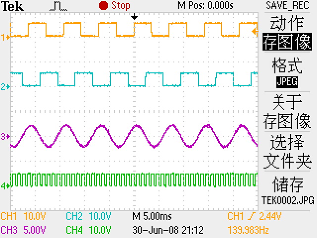
now , let me come to eliminate the suspicion of my analog comparator board. The graph below is get by this condition:
1 the motor(FL42BLS01-001) is drived by another running motor wholly, that means no electronical power directly give to the motor we test(FL42BLS01-001) to reduce noise signal except the BEMF.
2 the phase A(input) of my analog comparator board is connect to the phase A of FL42BLS01-001.
3 the output (sensorless A,B) of my analog comparator connect to the Tektronix TDS2024B's CH1 and CH2's probe.
CH1------sensorless A (output ) of analog comparator
CH2------sensorless B (output ) of analog comparator
CH3------Phase A of motor
CH4------1KHz 5V square wave suppled by TDS2024B
the waves of phaseb,c and sensorless c is correspondig to the wave displayed in graph below except the phase degree.
the waves of phaseb,c and sensorless c is correspondig to the wave displayed in graph below except the phase degree.
(原文件名:ourdev_332273.JPG)
so conclude that my analog comparator board is ok. Is it right?
The problem have afflict me for almost three days. In the three days I never go to bed befor 4 clock in morning. I really thanks for your help.
2008-07-02
第三封
sorry, I add one clue.
I found that in avr492
switch(position)
{
// cases according to rotor position
case HS_001: if (direction==CCW) {Set_Q1Q6();}
else {Set_Q5Q2();}
break;
case HS_101: if (direction==CCW) {Set_Q3Q6();}
else {Set_Q5Q4();}
break;
case HS_100: if (direction==CCW) {Set_Q3Q2();}
else {Set_Q1Q4();}
break;
case HS_110: if (direction==CCW) {Set_Q5Q2();}
else {Set_Q1Q6();}
break;
case HS_010: if (direction==CCW) {Set_Q5Q4();}
else {Set_Q3Q6();}
break;
case HS_011: if (direction==CCW) {Set_Q1Q4();}
else {Set_Q3Q2();}
break;
default : break;
}
but in avr493
switch(position)
{
// cases according to rotor position
case HS_001: if (direction==CCW) {Set_Q1Q6();}
else {Set_Q5Q2();}
break;
case HS_101: if (direction==CCW) {Set_Q3Q6();}
else {Set_Q5Q4();}
break;
case HS_100: if (direction==CCW) {Set_Q3Q2();}
else {Set_Q1Q4();}
break;
case HS_110: if (direction==CCW) {Set_Q5Q2();}
else {Set_Q1Q6();}
break;
case HS_010: if (direction==CCW) {Set_Q5Q4();}
else {Set_Q3Q6();}
break;
case HS_011: if (direction==CCW) {Set_Q1Q4();}
else {Set_Q3Q2();}
break;
default : break;
}
they are different.
in avr493 ,analog comparator boad replaced hall, and they function same to give out location of rotor.
but why the commutation sequence is different?
although I have coppied the avr492 commutation sequence into avr493, it still run and stop, run and stop ,again and again. |
|


 发表于 2008-7-2 19:01:38
 楼主
楼主