|
|
Oscilloscope Mk 1 Designs
Sunday, 07 September 2008 15:04
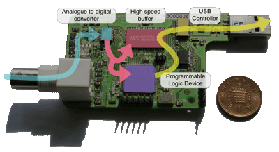
Following the interest garnered by the article I posted to this site about my USB oscilloscope design, I have decided to release the designs under an open-source Creative Commons licence.
(原文件名:oscilloscope_flow_diagram.gif)

(原文件名:oscilloscope.png)
Please note: To do this you are going to need to be reasonably competent in electronics, and capable of diagnosing the device to ensure everything's 'OK' before plugging it into your prized computer with all your precious data on. I accept no liability and offer no guarantees!
The downloads for this project can be found at the bottom of the page.
Schematics and PCB
The electronics for this were designed using CadSoft's EAGLE software package, and updated using version 5. You can download the freeware version to view the files and alter the circuit layout, however because it is multi-sheet the schematic will need a paid version to be edited.
Manufacture
There are many different board houses who now offer relatively low-cost one-off or prototype PCB production (see CadSoft's site for those that will accept EAGLE files, or Gerber plots can be created from within EAGLE for those that don't). Essentially you need to find one that can cope with a track/gap width accuracy of 0.2mm (8 thousandths of an inch) or better, to cope with the surface mount devices in the design.
When it comes to populating the board those fine-pitched surface mount components will come back to bite you! Many board houses also provide a prototype assembly service which may be worth considering. In the UK a £50 setup charge is typically levied so getting them to mount the worst 7 ICs is likely to cost you £60-£70, but may well be worth putting up with.
The alternative is to solder them yourself, which is possible and is how I've tended to do it. Both times I have been fortunate enough to be able to borrow a binocular microscope, but at the least you will need a good pair of magnifiers. Then arm yourself with some solder paste and the finest soldering iron bit that you can buy. Lay down a line of solder paste around the edge of the IC footprint (you don't need to worry about it being across the pads). Place the IC down and line it up (use a pair of tweezers, or a screwdriver with a blob of "blu-tack" on the end is great for square packages) then heat two opposite corner pins to fix the chip in place. Now go around the chip carefully heating each pin in turn. You will find that as you heat the pin the little spheres of solder in the paste are drawn up towards the pin, leaving very little solder behind after you've done all the pins, and what is left can easily be brushed out of the way.
HINT: I have found that the low-pass anti-aliasing filter is not really useful in the context of an oscilloscope design. You would therefore be advised not to fit R8, R11, C9, C26, C27, L2, L3, L4 and to bridge solder-jumper SJ1 from pad 3 to 2. To compensate for the loss of attenuation from the filter change R6 to a 1K precision resistor.
Set the potentiometer R13 to somewhere in the middle of its range (exactly where doesn't matter at this point). Once you've completed the setup and plugged it into the software you will want to adjust R13 to adjust the voltage offset.
PIC Programming
The design includes a PIC microcontroller (16F690) which plays a simple supervisory role, loading in settings sent down from the computer over the USB and clocking them into the control registers on the CPLD. The header JP2 on the PCB is a standard layout ICSP connector, which is used to program the PIC from either Microchip's free MPLAB software, Hi-Tech's HI-TIDE or one of the PIC programs from this site in conjunction with an appropriate programmer.
CPLD Programming
The majority of the work in the oscilloscope is done by a Xilinx programmable logic IC (a XCR3128XL CoolRunner 2 CPLD). This was done using Xilinx's free WebPack version of their ISE software (I used version 7) using a combination of schematic entry and some VHDL code.
The CPLD is programmed using a JTAG header (JP1) with Xilinx's standard JTAG pin-out. If you have a PC, the patience to download the software (it's several gigabytes!) and a programmer (Xilinx has a simple parallel port design on its web site somewhere) then this is probably the most reliable way to program the chip.
USB Controller Configuration
The final task with the hardware is to configure the USB controller IC. The good news is that no special programmer is needed and the software is free. The bad news for some is that a copy of Windows is needed (to investigate other techniques see FTDI's web site).
First install the Windows drivers from here: http://www.ftdichip.com/Drivers/D2XX.htm (you'll need to do this to run the Oscilloscope anyway (if you're planning to use it on Windows!) then install FTDI's MProg software from here: http://www.ftdichip.com/Resources/Utilities/MProg3.0_Setup.exe
Finally plug the oscilloscope into a USB port (you may want to do some other tests on it before doing this and blowing up your computer - don't worry that really shouldn't happen) then load this config file into the MProg program and click the lightning bolt icon to 'program all existing devices' (Note: You may want to ensure you don't have any other devices plugged in which may be using FTDI's USB controllers!).
Windows should then go through the 'found new hardware' malarky announcing that its found an 'USB Oscilloscope'. Congratulations, you're almost there!!
Software
If you're using a different computer to run the scope or you didn't do so in the step above, then you need to install the appropriate D2XX drivers from FTDI's web site http://www.ftdichip.com/Drivers/D2XX.htm
Finally install the software (downloads below) and run it. Click the little circular arrows button to discover all connected scopes - and enjoy!
Finally
If you follow this through and succeed then congratulations, and please let me know including any feedback you have on these instructions. If you make any alterations to the design please bear in mind the conditions of the license, and I would be grateful if you could supply either the new designs or a link to them so that I can offer them here.
Attachments: Oscilloscope Logic.zip [Pre-compiled CPLD Logic Files (JED/XSVF)] 10 Kb 14/03/09 22:22
Oscilloscope_BOM_RevB.xls [Bill of materials (Excel) - UK Suppliers] 75 Kb 14/03/09 22:05
Osc_EAGLE_files.zip [Schematics and Board Layout (EAGLE)] 582 Kb 14/03/09 22:05
Osc_PIC_Firmware.hex.zip [Pre-compiled HEX file (for PIC)] 0 Kb 14/03/09 22:07
Osc_PIC_source.zip [PIC Firmware Source Files] 2 Kb 14/03/09 22:07
Osc_Prog_Logic.pdf [Logic schematics & design (PDF)] 143 Kb 14/03/09 22:13
Osc_RB_Source.zip [Software source (REALbasic)] 312 Kb 14/03/09 22:18
Osc_Software_MacIntel.zip [Oscilloscope Software (Mac Intel)] 1443 Kb 14/03/09 22:17
点击此处下载 ourdev_434763.pdf(文件大小:143K) (原文件名:032_Osc_Prog_Logic.pdf)
点击此处下载 ourdev_434764.xls(文件大小:75K) (原文件名:032_Oscilloscope_BOM_RevB.xls)
点击此处下载 ourdev_434765.zip(文件大小:583K) (原文件名:032_Osc_EAGLE_files.zip)
点击此处下载 ourdev_434766.zip(文件大小:567字节) (原文件名:032_Osc_PIC_Firmware.hex.zip)
点击此处下载 ourdev_434767.zip(文件大小:2K) (原文件名:032_Osc_PIC_source.zip)
点击此处下载 ourdev_434768.zip(文件大小:312K) (原文件名:032_Osc_RB_Source.zip)
点击此处下载 ourdev_434769.zip(文件大小:312K) (原文件名:032_Osc_RB_Source.zip)
点击此处下载 ourdev_434770.zip(文件大小:1.41M) (原文件名:032_Osc_Software_MacIntel.zip)
点击此处下载 ourdev_434771.zip(文件大小:10K) (原文件名:032_Oscilloscope Logic.zip) |
阿莫论坛20周年了!感谢大家的支持与爱护!!
月入3000的是反美的。收入3万是亲美的。收入30万是移民美国的。收入300万是取得绿卡后回国,教唆那些3000来反美的!
|


 发表于 2009-4-9 19:27:05