|
|
使用BASCOM-AVR(1.11.7.4版)编写简单的16*2 LCD 测试程序。通过。
源代码:
'$sim 正式下载到目标板上时,必须清除该语句,重新编译!!
'$sim 语句应用于加快BASCOM-AVR软件仿真的速度 is used fr faster simulation
'define chip to use
$regfile = "M16def.dat"
'define used crystal
$crystal = 4000000
'note : tested in PIN mode with 4-bit LCD工作于 4位PIN方式
Config Lcdpin = Pin , Db4 = Porta.4 , Db5 = Porta.5 , Db6 = Porta.6 , Db7 = Porta.7 , E = Porta.0 , Rs = Porta.1
Dim A As Byte
Config Lcd = 16 * 2 'configure lcd screen
Cls 'clear the LCD display
Lcd "Hello Ouravr." 'display this at the top line
Wait 1
Lowerline 'select the lower line
Wait 1
Lcd "Shift this." 'display this at the lower line
Wait 1
For A = 1 To 15
Shiftlcd Right 'shift the text to the right
Wait 1 'wait a moment
Next
For A = 1 To 15
Shiftlcd Left 'shift the text to the left
Wait 1 'wait a moment
Next
End
程序运行情况:
在第一行显示“Hello Ouravr.”
等1秒
在第二行显示“Shift this.”
等1秒
每隔1秒整个屏幕显示的内容向右移动一个字符
每隔1秒整个屏幕显示的内容向左移动一个字符
结束
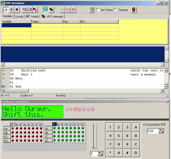
在BASCOM-AVR中使用软件模拟仿真的情况:
在M16板上的连接方式:
使用短路片短路M16边上的:
PB5、PB6、PB7、RST(以上为ISP口);
VCC、GND;
X2、X1(使用内部震荡可不短路);
PD0、PD1(不同PC通信时可不连);
AVCC、GND(在M16的右边);
如使用外部晶体时:JN(连AVR)、J1(连4M);
JB1(接通LCD电源5v);
用7根连接线:
PA0-->LCD_E
PA1-->LCD_RS
GND-->LCD_R/W
PA4-->LCD_Db4
PA5-->LCD_Db5
PA6-->LCD_Db6
PA7-->LCD_Db7
首先使用ISP下载线对M16的熔丝位配置(建议使用BASCOM-AVR中的下载软件,非常直观):
禁止JTAG口,PORTC全部作为I/O使用;
使用外部晶体或内部RC振荡(根据需要);
允许BOD检测,门限电压4.0v;
RESET向量为0x0000(确省值为0X0000,一般不用改)。
-----此内容被machao于2005-02-27,00:57:08编辑过 |
|


 发表于 2005-2-26 21:49:38
 楼主
楼主