|
|

楼主 |
发表于 2010-12-7 14:37:53
|
显示全部楼层
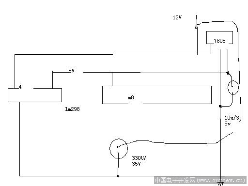
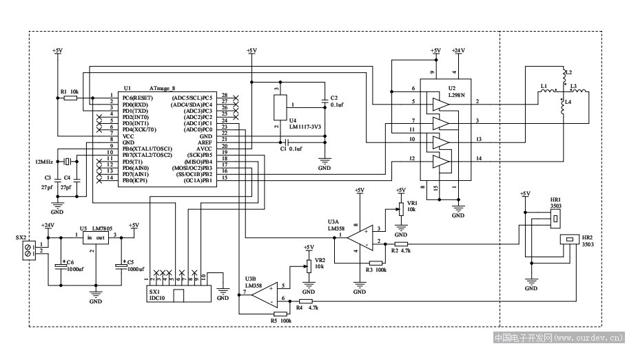
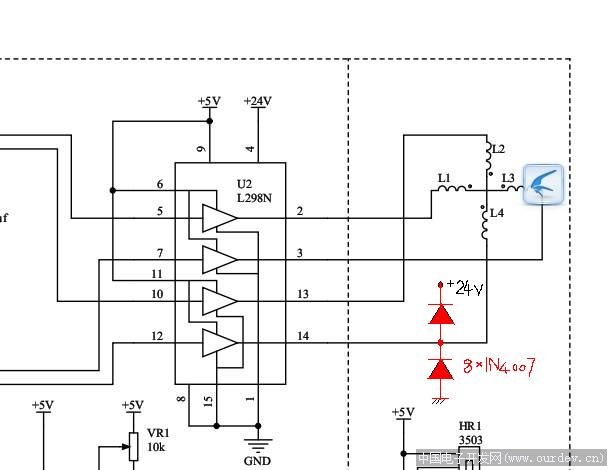
二极管接了,8个IN4017.
(原文件名:L298N.jpg)
仅画了3个二极管。
24V 实际试验时是12V。
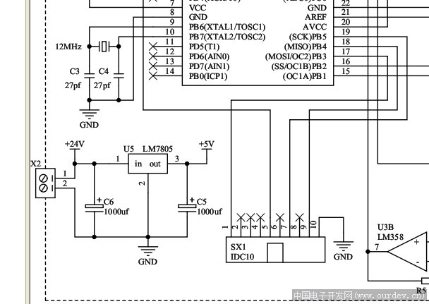
(原文件名:了吗24.jpg)
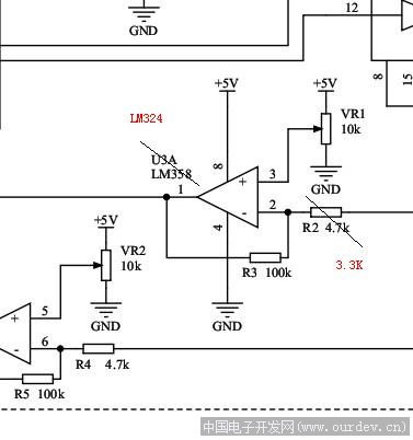
运放使用的是LM324 输出调为:1.65V, 4.7K 改为3.3K。
程序根据电路图做了适当的调整:
//#define CA _PD1 //对应 PB1 控制一组线圈
//#define CB _PD0 //对应 PB2 控制一组线圈
不需要的代码,在原始的基础上,禁止了!!!
=====================================================================
//源程序公开:
//--------------------------------------------------------------------------
//下推式磁悬浮源程序 2009.12.18
//liguang70217
//liguang70217@126.com
//http://liguang70217.blog.hexun.com/
//ICC-AVR application builder : 2009-12-17 17:27:22
// Target : M8
// Crystal: 12.000Mhz
//--------------------------------------------------------------------------
#include <iom8v.h>
#include <macros.h>
#include"BIT.h"
//#define LED_A _PB0
//#define LED_B _PB1 //发光二极管指示
//#define CA _PD1 //对应 PB1 控制一组线圈
//#define CB _PD0 //对应 PB2 控制一组线圈
#define N 7
#define MAX_PID_OUTPUT 950
#define MAX_INTEGRATION_ERROR 100
//#define X_DIRECTION_FLAG 0x01
//#define Y_DIRECTION_FLAG 0x02
//定义一个结构--------------------------------------------------------------------------
typedef struct {
int targetValue;
int Kp;
int Ki;
int Kd;
int integrationError;
int prevError;
} PID;
PID xPID,yPID;
//unsigned char direction;
unsigned char ix=0,iy=0;
unsigned int value_buf_x[N],value_buf_y[N];
unsigned int xpos,ypos; //AD转换后存放采集值
//unsigned char HH;
//unsigned int xError, yError;
//unsigned int xPWM, yPWM;
//--------------------------------------------------------------------------
//------------延时子程序----------------------------------------------------
//void delay(unsigned int h)
//{
//unsigned char j;
//while(h--){ for(j=190;--j;) continue; }
//}
//--------------------------------------------------------------------------
// PID calculation routine
int calcPID(PID *pid, int error)
{
int output;
if (pid->Ki != 0)
{
pid->integrationError += error;
// Limit the maximum integration error
if (pid->integrationError > MAX_INTEGRATION_ERROR)
{ pid->integrationError = MAX_INTEGRATION_ERROR; }
else if (pid->integrationError < -MAX_INTEGRATION_ERROR)
{ pid->integrationError = -MAX_INTEGRATION_ERROR; }
}
output = pid->Kp * error + pid->Ki * pid->integrationError + pid->Kd * (error - pid->prevError);
// Limit the maximum output
if (output > MAX_PID_OUTPUT)
{ output = MAX_PID_OUTPUT; }
else if (output < -MAX_PID_OUTPUT)
{ output = -MAX_PID_OUTPUT; }
pid->prevError = error;
return output;
}
//--------------------------------------------------------------------------
void port_init(void)
{
PORTB = 0xff;
DDRB = 0xff; //输出
PORTC = 0x00; //m103 output only
DDRC = 0x00; //输入,adc采集
PORTD = 0x00;
DDRD = 0xff; //输出
}
//--------------------------------------------------------------------------
//TIMER1 initialize - prescale:1
// WGM: 7) PWM 10bit fast, TOP=0x03FF
// desired value: 2KHz
// actual value: 11.719KHz (82.9%)
void timer1_init(void)
{
TCCR1B = 0x00;//停止定时器
TIMSK |= 0x00;//中断允许
TCNT1H = 0x00;
TCNT1L = 0x00;//初始值
OCR1AH = 0x01;
OCR1AL = 0xFF;//匹配A值
OCR1BH = 0x01;
OCR1BL = 0xFF;//匹配B值
ICR1H = 0xFF;
ICR1L = 0xFF;//输入捕捉匹配值
TCCR1A = 0xA3;
TCCR1B = 0x09;//启动定时器
}
//--------------------------------------------------------------------------
//call this routine to initialize all peripherals
void init_devices(void)
{
//stop errant interrupts until set up
CLI(); //disable all interrupts
MCUCR = 0x00;
MCUCSR = 0x80;//禁止JTAG
GICR = 0x00;
port_init();
timer1_init();
// TIMSK = 0x04; //timer interrupt sources
SEI(); //re-enable interrupts
//all peripherals are now initialized
//----------------------------------
//unsigned int ZD;
//unsigned int ccc;
//ZD=511;
// PID Parameter Initialization
xPID.Kp = 4;
xPID.Ki = 0;
xPID.Kd = 30;
//xPID.integrationError = 0;
//xPID.prevError = 0;
//xPID.targetValue = ZD;
//.......................................
yPID.Kp = 4;
yPID.Ki = 0;
yPID.Kd = 30;
//yPID.integrationError = 0;
//yPID.prevError = 0;
//yPID.targetValue = ZD;
//------------------------------------
}
//ADC,Analog-to-Digital Converter的缩写,指模/数转换器或者模拟/数字转换器-----------------------------------------------------------------------------
unsigned int get_ad(unsigned char k) //k 为ADC采样端口号
{
union adres{ int k1; unsigned char adre[2]; }adresult;
//unsigned int i;
ADMUX = 0xc0+k; /*基准AVCC、左对齐、通道7*/
ADCSRA = 0xC3; /*使能、开启、8分频*/
while(!(ADCSRA & (1 << ADIF))); /*等待*/
adresult.adre[0]=ADCL; //读取并存储A/D转换结果,A/D转换的结果通过共
adresult.adre[1]=ADCH; //用体的形式放入了变量k1中
ADCSRA &= ~(1 << ADIF); /*清标志*/
ADCSRA &= ~(1 << ADEN); /*关闭转换*/
return adresult.k1;
}
//--------------------------------------------------------------------------
//x:滑动平均滤波
unsigned int filter_x(void)
{
unsigned char count;
unsigned long sum=0;
value_buf_x[ix] = get_ad(0); //ADC采样函数,采样第0通道信号,采样分辨率256
ix=ix+1;
if ( ix == N ) ix = 0;
for ( count=0;count<N;count++)
sum = sum + value_buf_x[count];
return (unsigned int)(sum/N);
}
//--------------------------------------------------------------------------
//y:滑动平均滤波
unsigned int filter_y(void)
{
unsigned char count;
unsigned long sum=0;
value_buf_y[iy] = get_ad(1);//ADC采样函数,采样第1通道信号,采样分辨率256
iy=iy+1;
if ( iy == N ) iy = 0;
for ( count=0;count<N;count++)
sum = sum + value_buf_y[count];
return (unsigned int)(sum/N);
}
//-----------------------------------------------------------------------------
void main(void)
{
init_devices();
//OCR1A 和 TCNT1 比较匹配发生时OC1A 寄存器将产生相应的清零或置位操作,从而产生PWM 波形。
//OCR1B 和 TCNT1 比较匹配发生时OC1B 寄存器将产生相应的清零或置位操作,从而产生PWM 波形。
//工作于相位修正PWM 模式时,比较单元可以在OC1x 引脚(PB1,PB2)输出PWM 波形。要真正从物理引脚上输出信号还必须将OC1x 的数据方向设置为输出。
while(1)
{
xpos=filter_x(); //x轴位置检测
//xpos=555;
ypos=filter_y(); // y轴位置检测
//ypos=555;
//PB1 OC1A (T/C1 输出比较匹配 A 输出 )
//OC1A – 端口 B, Bit 1
//OC1A ,输出比较匹配输出:PB1 引脚作为 T/C1 比较匹配 A 的外部输出。此时,PB1 引脚 将设置为输出。
//OC1A 引脚在 PWM 模式定时器功能时作为输出引脚。
if(xpos>511)
{
//xpos = xpos-ZD;
//xError = xPID.targetValue - xpos;
//xPWM = calcPID(&xPID, xError);
//OCR1A = xPWM; //输出比较器 PB1
//OCR1A = calcPID(&xPID, xPID.targetValue - (xpos-ZD)); //输出比较器 PB1
//OCR1A = calcPID(&xPID, 2*ZD - xpos); //输出比较器 PB1
OCR1A = calcPID(&xPID, 2*511 - xpos); //输出比较器 PB1
//........................
//CA=1; //_PD1 //对应 PB1 控制一组线圈
//_PD1=1;
//PORTD=1<<PD1;//PD1=1
PORTD|=(1<<1); //CA=1
}
else
{
//xpos = ZD-xpos;
//xError = xpos;
//xPWM = calcPID(&xPID, xError);
//OCR1A = xPWM; //输出比较器 PB1
OCR1A = calcPID(&xPID, 511-xpos); //输出比较器 PB1
//.........................................
//CA=0; //_PD1 //对应 PB1 控制一组线圈
//_PD1=0;
//PORTD=0<<PD1;//PD1=0
PORTD&=~(1<<1); //CA=0
}
//------------------------------------------------------
if(ypos>511)
{
//ypos = ypos-ZD;
//yError = yPID.targetValue - ypos;
//yPWM = calcPID(&yPID, yError);
//OCR1B = yPWM; //输出比较器PB2
//OCR1B = calcPID(&yPID, yPID.targetValue - (ypos-ZD)); //输出比较器PB2
//OCR1B = calcPID(&yPID, 2*ZD - ypos); //输出比较器PB2
OCR1B = calcPID(&yPID, 2*511 - ypos); //输出比较器PB2
//..........................
//CB=1; //_PD0 //对应 PB2控制一组线圈
//_PD0=1;
//PORTD=1<<PD0;//PD0=1
PORTD|=(1<<0); //CB=1
}
else
{
//ypos = ZD-ypos;
//yError = ypos;
//yPWM = calcPID(&yPID, yError);
//OCR1B = yPWM; //输出比较器PB2
//OCR1B = calcPID(&yPID, ZD-ypos); //输出比较器PB2
OCR1B = calcPID(&yPID, 511-ypos); //输出比较器PB2
//.................................................
//CB=0; //_PD0 //对应 PB2 控制一组线圈
//_PD0=0;
//PORTD=0<<PD0;//PD0=0
PORTD&=~(1<<0); //CB=0
}
}
}
//---------------------------------------------------------------------------- |
|


 发表于 2010-12-7 08:38:45