|
|
潜水了那么久,总算觉得有点谱了,可以动手搭个洞洞板和谢谢程序了。发在这里觉得内容相关,并且如果不写下来的话,很快就会忘记曾经做过什么了,就当是DIY调试笔记好了。 偶菜鸟一个,基本上一切电调的只是都是来源ourdev和google, 在此特别感谢timegate,《无感无刷直流电机之电调设计全攻略》简直就是我的红宝书。好了,废话少说,开始调试笔记。
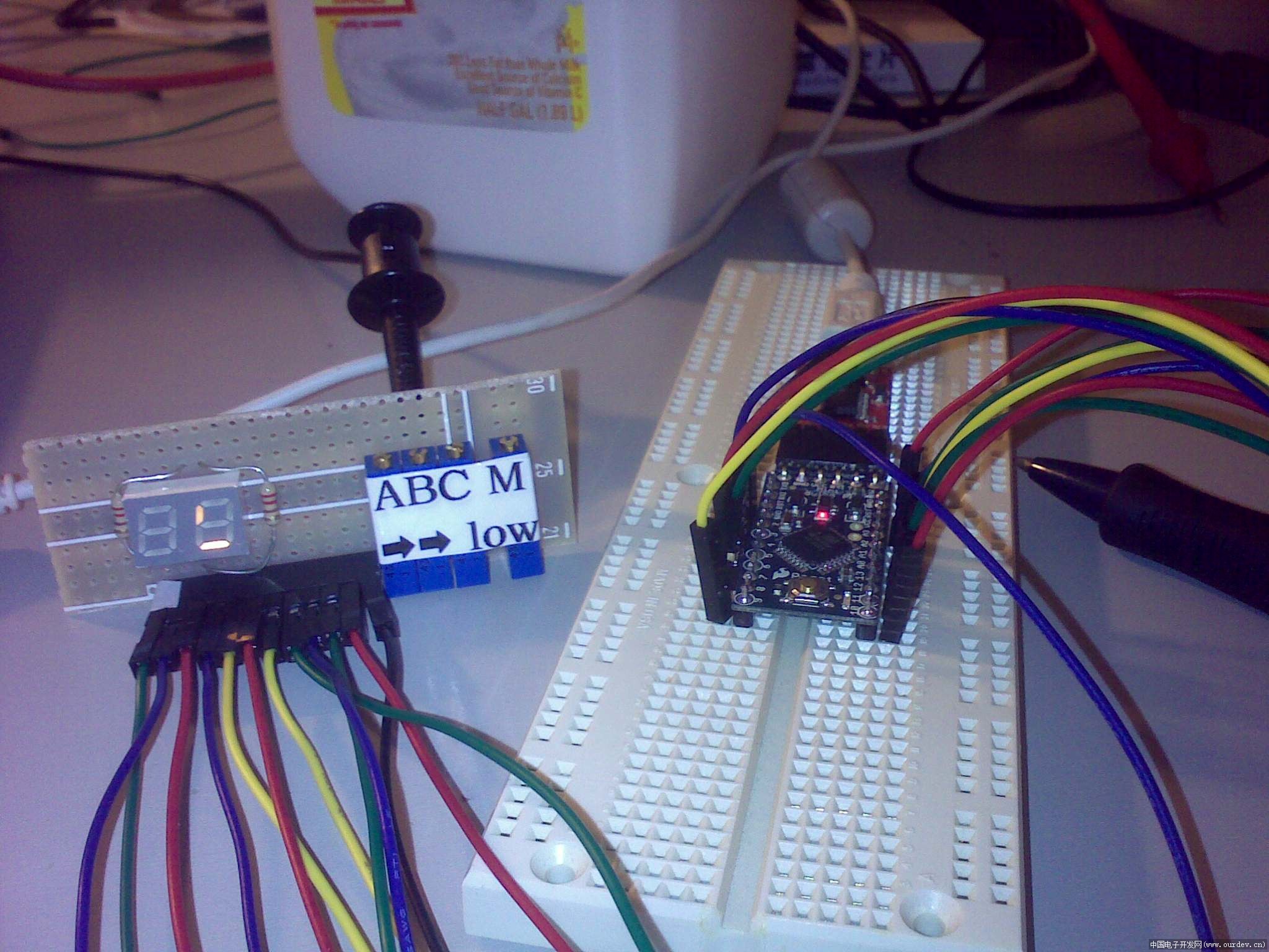
因为从来没用过avr,因此觉得还是买个现成的产品比较方便,找来找去,买了个Arduino mini pro, 5V/16MHz。本来想着挺好的,有编译环境,带了bootloader,应该挺方便的。结果恰恰相反,这个Arduino编译环境给我整了不少麻烦。
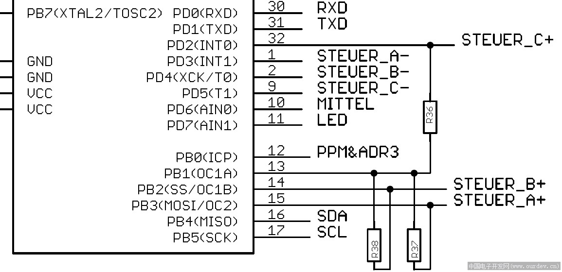
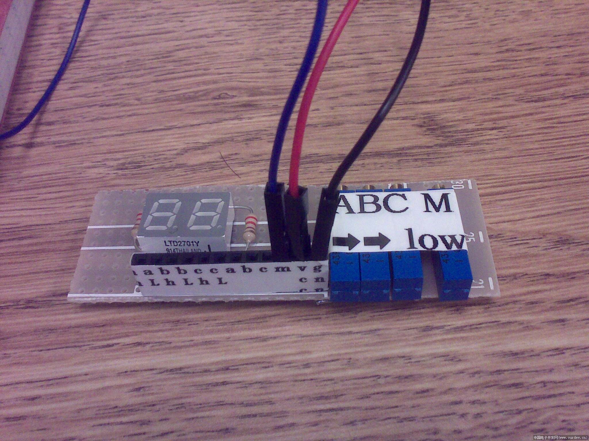
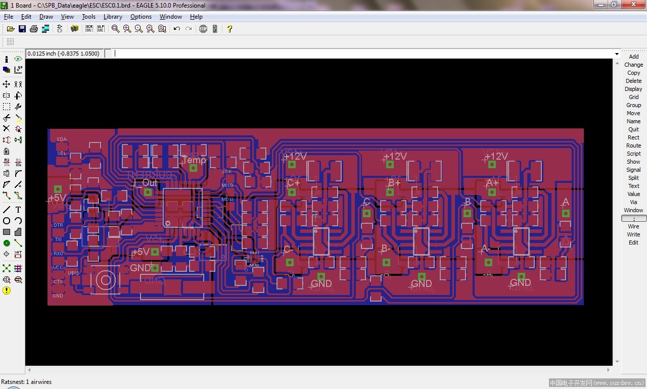
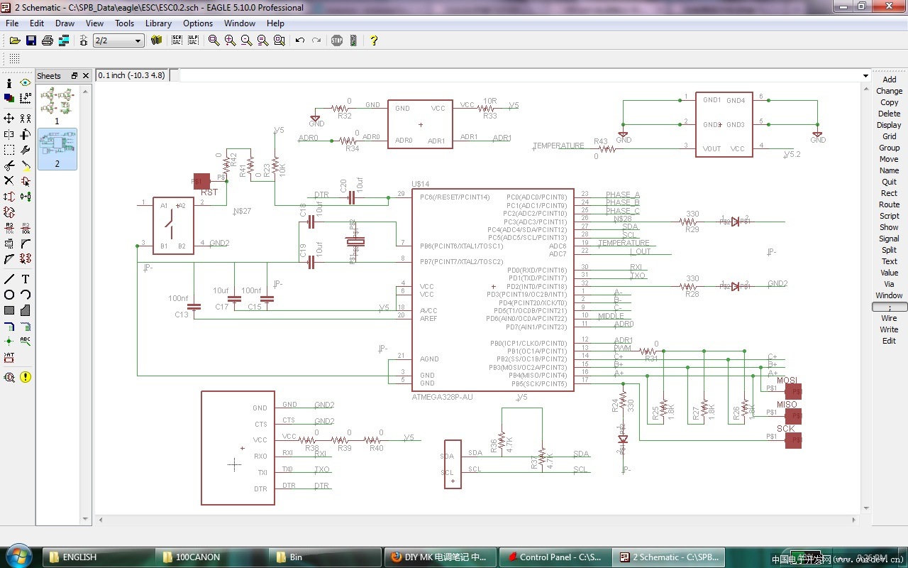
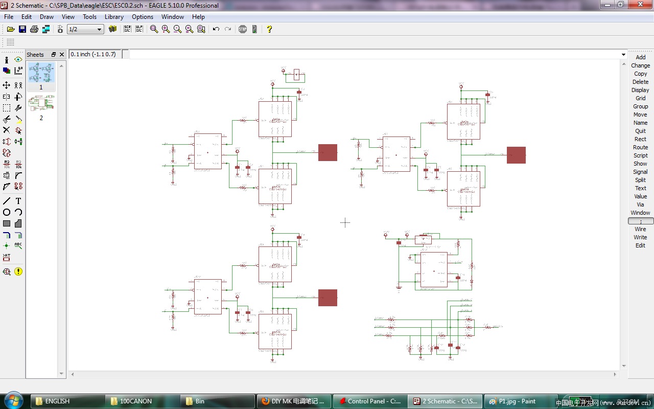
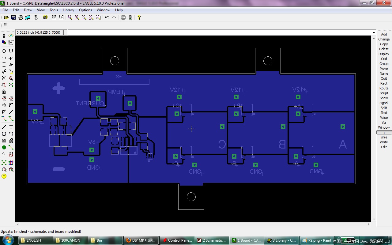
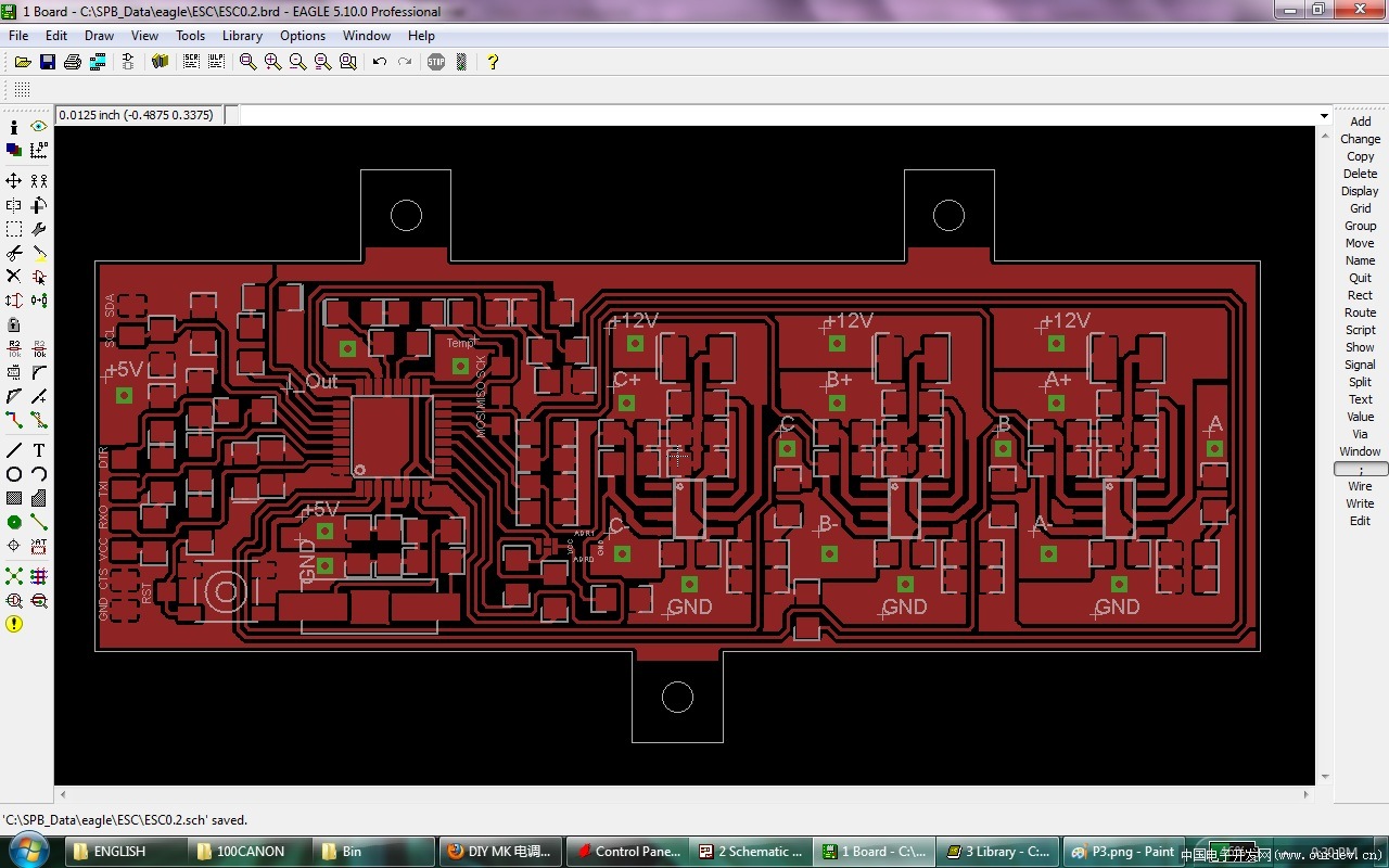
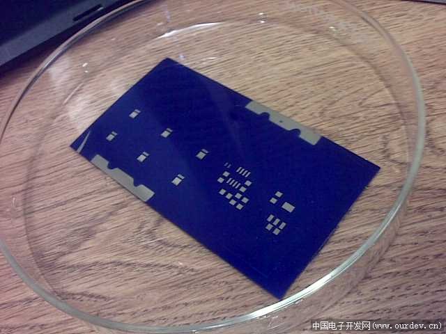
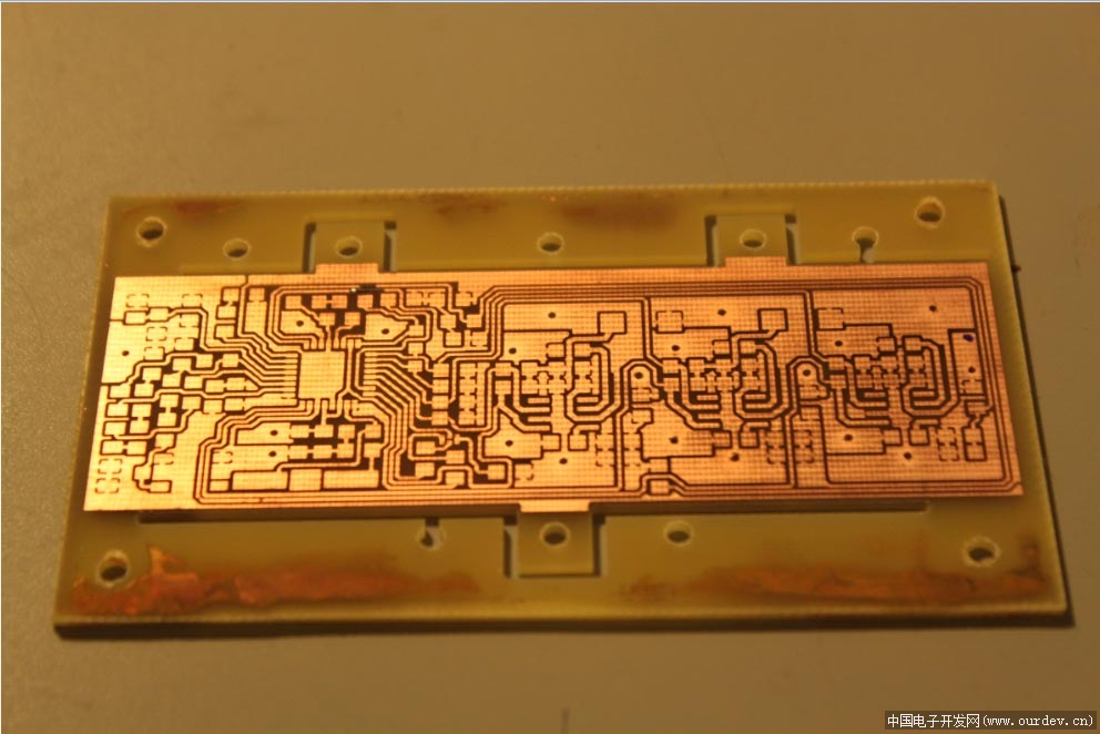
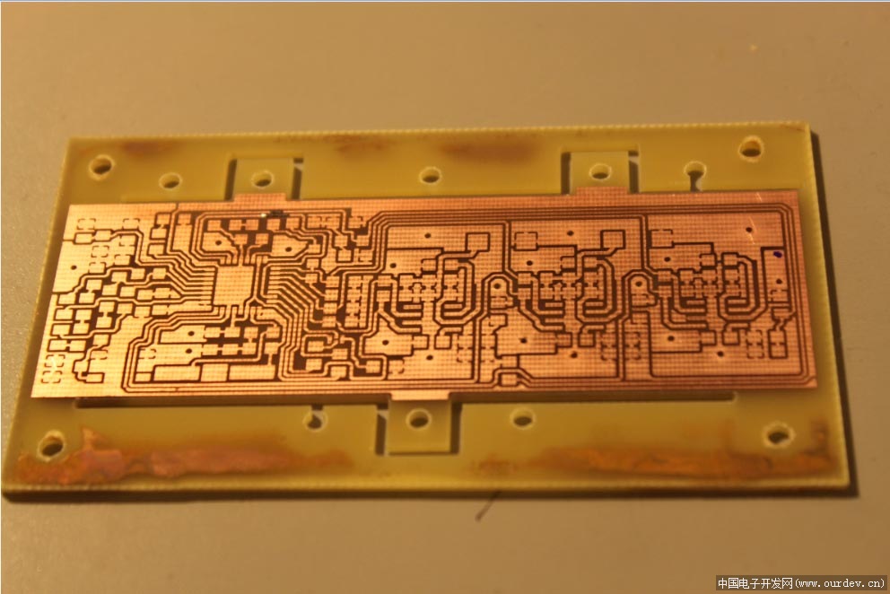
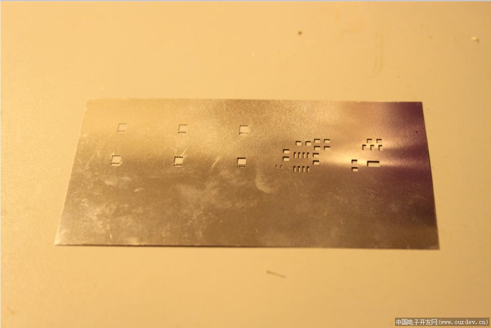
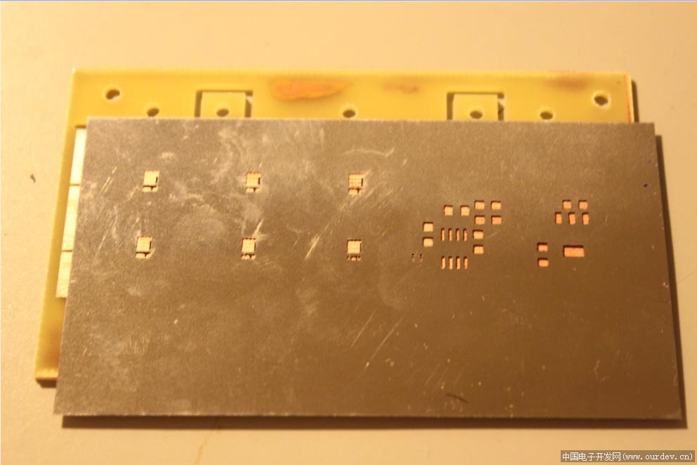
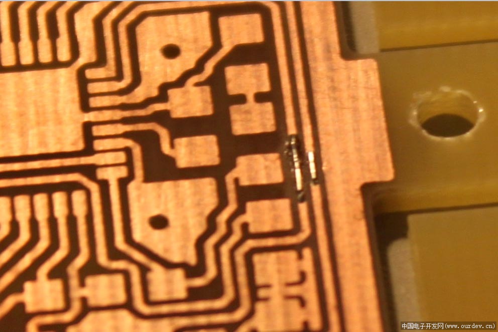
我的思路是基本上沿用MK V1.2硬件,0.41的软件的路子,用不同的MCU和功率管。想用的功率管还没到,简单的搭了一个能让硬盘电机转的板子,大约3A的能力,觉得暂时够调试用了。MCU用的是arduino mini pro 328,这个16MHz的ATmega328P甚是麻烦。首先是16MHz,所有涉及分频的部分都要改。另外这个328和mega8有大量的寄存器不同,代码基本上不能直接Ctrl+V。不过也好,知道每一行代码的功能。
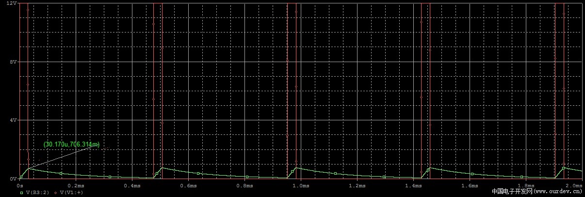
今天主要熟悉了一下编译环境,尝试着写了一下timer0的设定,and using the overflow interrupt to achieve timed delay in millisecond range.
Some comments:
1. TCCR0 register has been rearranged to TCCR0B register. The lower three digits reserve the functionality original TCCR0 register.
2. The keyword of timer0 overflow interrupt, SIG_OVERFLOW0, changes its name from SIG_OVERFLOW0 in WinAVR to TIMER0_OVF_vect.
3. However, there will be a conflict while compiling. I just backed up the "wiring.c" file and cleared the content of the file.
4. In original MK code, the MCU is running at 8MHz, prescaler is CLK/8. Then, 4 timer0 overflow is actually 1ms. In 16MHZ nmega328, just the timer0 prescaler of CLK/64 will have the 1ms overflow interval.
5. The "volatile" property is important to avoid possible faulty compiler optimization.
That's it,the timer seems working well...
2011.04.02 |
阿莫论坛20周年了!感谢大家的支持与爱护!!
月入3000的是反美的。收入3万是亲美的。收入30万是移民美国的。收入300万是取得绿卡后回国,教唆那些3000来反美的!
|
 [复制链接]


 发表于 2011-4-3 10:43:39
 楼主
楼主