|
|

楼主 |
发表于 2008-4-12 23:19:31
|
显示全部楼层
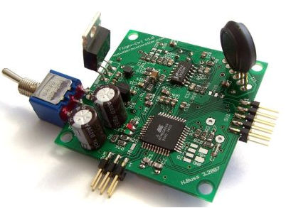
Parts soldering 元件焊接
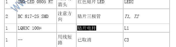
The parts should be soldered in the same order as shown in the listing. This simplifies the task. 元件应该按照下表的顺序进行焊接。这可以简化任务。
Parts in italics are placed on the solder side (bottom) 斜体字的元件放置在焊接面(背面)
Qty Reichelt Order# Remark Part Name
数量 货号 备注 零件 名称
-----------------------------------------------------------------------------------------------------------------------------
1 ATMEGA 644-20 AU Check origin注意产地 VR-RISC-Controller IC1
1 TS 914 I SMD Check origin注意产地 Rail to Rail Op-Amp 轨到轨运放 IC2
5 NPO-G0805 22P Capacitor电容 C1, C2, C28, C29,C30
5 X7R-G0805 22N Capacitor电容 C9, C15, C17, C27,C31
5 X7R-G0805 22N Capacitor电容 C9, C15, C17, C27, C31
17 X7R-G0805 100N Capacitor电容 C5, C6, C8, C12, C13, C16, C18, C19, C20,
C21, C11, C22, C14, C23, C24, C25, C26
5 SMD-0805 1,00K SMD-Chip-resistor贴片电阻 R2, R5, R6, R7, R4
5 SMD-0805 100 SMD-Chip-resistor贴片电阻 R24, R27, R28, R32, R33
5 SMD-0805 10,0K SMD-Chip-resistor贴片电阻 R8, R12, R16, R1, R3
4 SMD-0805 100K SMD-Chip-resistor贴片电阻 R10,R11, R14, R18
1 SMD-0805 220K SMD-Chip-resistor贴片电阻 R26
1 SMD-0805 2,20K SMD-Chip-resistor贴片电阻 R25
1 SMD-0805 6,80K SMD-Chip-resistor贴片电阻 R21
3 SMD-0805 18,0K SMD-Chip-resistor贴片电阻 R22, R30, R31
1 SMD-0805 680 SMD-Chip-resistor贴片电阻 R19
1 SMD-LED 0805 GN Arrow on bottom底部有箭头 CHIP-LED green绿色贴片LED LED1
1 SMD-LED 0805 RT Arrow on bottom底部有箭头 CHIP-LED red红色贴片LED LED2
2 BC 817-25 SMD Check direction注意方向 CHIP-Transistor贴片三极管 T1, T2
1 LQH3C 100µ SMD-Inductor贴片电感 L1
1 -- Short with wire用线短路 omitted已取消 C3
1 1N 4001 Check marking注意标记 Diode二极管 D1
1 20,0000-HC49U-S Quartz 20,0MHz晶振 Q1
1 LP 2950 ACZ3,0 Check marking注意标记 Voltage regulator +3,0V稳压器 IC5
1 µA 7805 Check marking注意标记 Voltage regulator稳压器 IC4
2 RAD 330/16 Check polarity注意极性 Electrolytic cap电解电容 C7, C10
1 MS 500F SolderToTheRim焊接到边缘 Switch, 2-pole单刀双掷开关 SW1 use wire if necessary
1 SL 2X10G 2,54 Divide in分割成2*3 & 2*5 Header two rows双排针 SV1, SV5
1 SUMMER TDB 05 Polarity:(+) to the rim Beeper蜂鸣器 SP1
of the board正极(+)位于
板的边缘
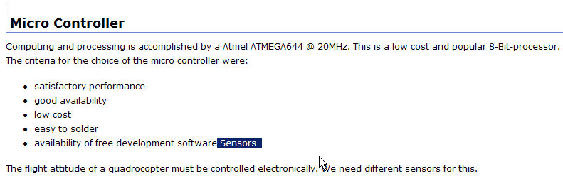
Sensors 传感器
数量 货号 备注 零件 名称
-----------------------------------------------------------------------------------------------------------------------------
1 LIS3L02AS4 Acceleration sensor加速度传感器 IC3
2 ENC-03JA Check direction注意方向 Gyros Pitch and Roll俯仰和滚动陀螺仪 GY_N, GY_R
1 ENC-03JA Check direction注意方向 Gyro Yaw偏航陀螺仪 GY_G
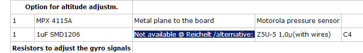
Option for altitude adjustm.高度调整可选件
数量 货号 备注 零件 名称
-----------------------------------------------------------------------------------------------------------------------------
1 MPX 4115A Metal plane to the board金属面朝向板 Motorola pressure sensor摩托罗拉压力传感器 V1
1 1uF SMD1206 Not available @ Reichelt /alternative: Z5U-5 1,0µ(with wires)Z5U-5 1,0µ(和导线) C4
Reichelt /alternative没有此零件销售
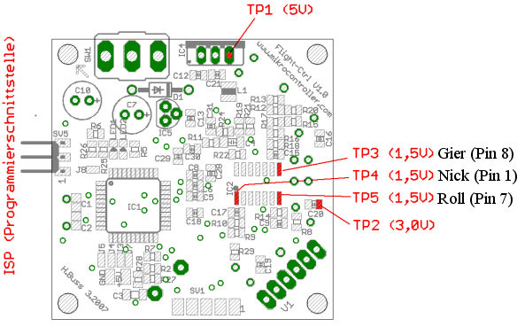
Resistors to adjust the gyro signals 用于调整陀螺仪的电阻
数量 货号 备注 零件 名称
-----------------------------------------------------------------------------------------------------------------------------
3 SMD-0805 470K See instructions见说明 SMD-Chip-resistor贴片电阻
3 SMD-0805 150K See instructions见说明 SMD-Chip-resistor贴片电阻
3 SMD-0805 220K See instructions见说明 SMD-Chip-resistor贴片电阻
Gyros, acceleration & pressure sensors are available in the Shop 在我们的商店可以买到陀螺仪、加速度和压力传感器。 |
|


 发表于 2008-4-12 22:33:28