搜索
bottom↓
回复: 15

Using timers on mid-range PICs

[复制链接]

出0入0汤圆

发表于 2009-9-5 18:33:40 | 显示全部楼层 |阅读模式
mid range pics have two timers, timer0 (8 bits) and timer1 (16 bits). the difficulties in using them come from determining various values.

the examples below give you a much simpler way to set up the timers. all you need to do is to tell the program timer parameters, and how long you want the timer to last and the rest is done by the compiler.

the program basically works by calculating the number of times a timer has to trigger (MaxCnt) based the mcu frequency (Fosc), prescaler setting (TMRScaler), and timer offset (TMROffset) determined by low long you want the timer to go (TimeuS).

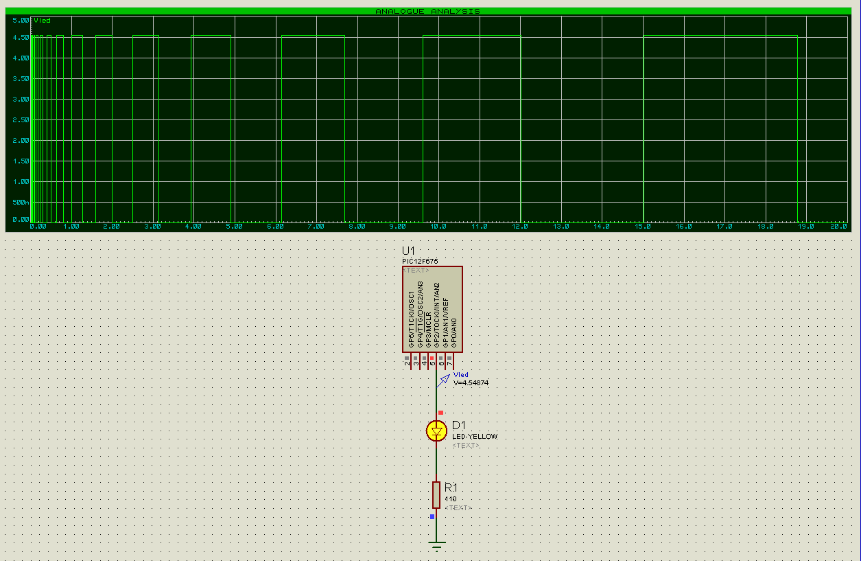
here is an example where we want the LED on GPIO2 to blink once every 1 seconds (Timeus=1000000us).

the hex file is 0x6c words long, :)


==========code==============
//use a counter to help adjust timing

#include <htc.h>

__CONFIG (MCLRDIS & UNPROTECT & BORDIS & WDTDIS & INTIO & PWRTEN);

//hardware configuration
#define nLED                2                                                        //LED on gpio2
#define Fosc                4000000UL                                        //mcu runs at 4mhz
#define TMROffset        0x1a                                                //Offset to Timer. May need manual tweaking
#define TMRCnt                (0xff-TMROffset)                        //timer overflows, in ticks. 8bit timer here
#define TMRScaler        2                                                        //timer set to overflow in 32 ticks
#define TMRTicks        (TMRCnt*TMRScaler)                        //how many times to produce a Timer interrupt
#define TMRTimeuS        (4*1000000UL/Fosc*TMRTicks)        //how many us elapsed between Timer interrupts
#define TimeuS                1000000UL                                        //desired time intervals, in us
#define MaxCnt                (TimeuS / TMRTimeuS)                //maximum count to achieve TimeuS
#define Error                (+2)                                                //error to correct for timing. May need manual tweaking

unsigned char sGPIO;        //shadow gpio

void interrupt LED(void) {
        static unsigned long TMRCounter=MaxCnt;                //initialize t0 counter. "static" to retain value
        TMR0+=TMROffset+Error;                                                //advance TMR by TMRCnt
        TMRCounter-=1;                                                                //decrement T0Counter by 1;
        if (TMRCounter==0) {
                TMRCounter=MaxCnt;                                                //reset T0Counter
                sGPIO ^=(1<<nLED);                                                //flash nLED pin
        }
        T0IF=0;                                                                                //clear the interrupt flag
}

void
main(void)
{
        TRISIO=~(1<<nLED);                //all gpio pins to input other than nLED
        OPTION=0b11010000;                //setting up the options register;
        //       1                         //GPPU: pull-up disabled
        //        1                         //INTEDG: interrupt on rising edge
        //         0                        //T0CS: timer0 source select - internal clock cycle
        //          1                   //T0SE: timer0 edge select - interrupt on high-to-low transisiton
        //           0                        //PSA: prescaler selected to timer0
        //            100                //PS2..0: prescaler rate select - 100=32.
                                                        //timer0 prescaler rates:
                                                        //000 = 1:2, 001 = 1:4, 010 = 1:8, 011 = 1:16
                                                        //100 = 1:32, 101 = 1:64, 110 = 1:128, 111 = 1:256
       
        //GPPU=1; INTEDG=1;T0CS=0;T0SE=1;PSA=0;

        //T1CON=0b00010001;                //setting up timer1
        //      0                                //unused
        //       0                                //TMR1GE: timer1 is not gated, if TMR1ON=1
        //        01                        //T1CKPS1..0: timer1 prescaler set to 1/2. 00=1:1, 01=1:2, 10=1:4, 11=1:8
        //          0                        //T1OSCEN: timer1 LP oscilator is off
        //           0                        //T1SYNC: ignored since TMR1CS=0;
        //            0                        //TMR1CS: timer1 clock source select bit to internal oscillator
        //             1                //TMR1ON: turn timer1 on
       
        sGPIO=0;                                //clear gpio pins
       
        TMR0=TMROffset+Error;                        //load up the timer offset
        T0IE=1;                                                        //enable timer 0 interrupt
        ei();                                                                //enable global interrupt. = GIE=1;
       
        while (1){
                //TODO Auto-generated main function
                GPIO=sGPIO;
        }
}


(原文件名:pic timer0.PNG)

出0入0汤圆

 楼主| 发表于 2009-9-5 18:37:36 | 显示全部楼层
the longest time this approach can count, using timer0 is approximately 256us/timer*256 (prescaler) * (2^32 (maxcnt is a 32-bit long int))= 281.5 million seconds, or about 9 years.

the shortest is determined by the ISR routine, maybe 10 instructions -> 40us.

出0入0汤圆

 楼主| 发表于 2009-9-5 18:40:32 | 显示全部楼层
here is the same program, using timer1 instead.

the longest time it can run on is 2^16 us (timer) * 8 (prescaler) * 2^32 (MaxCnt) = 2.2 billion seconds, or 71 years, :)

==============code=================
//use a counter to help adjust timing

#include <htc.h>

__CONFIG (MCLRDIS & UNPROTECT & BORDIS & WDTDIS & INTIO & PWRTEN);

//hardware configuration
#define nLED                2                                                        //LED on gpio2
#define Fosc                4000000UL                                        //mcu runs at 4mhz
#define TMROffset        0xf000                                                //Offset to Timer. May need manual tweaking
#define TMRCnt                (0xffff-TMROffset)                        //timer overflows, in ticks
#define TMRScaler        1                                                        //timer set to overflow in 32 ticks
#define TMRTicks        (TMRCnt*TMRScaler)                        //how many times to produce a Timer interrupt
#define TMRTimeuS        (4*1000000UL/Fosc*TMRTicks)        //how many us elapsed between Timer interrupts
#define TimeuS                2000000UL                                        //desired time intervals, in us
#define MaxCnt                (TimeuS / TMRTimeuS)                //maximum count to achieve TimeuS
#define Error                (+3)                                                //error to correct for timing. May need manual tweaking

unsigned char sGPIO;        //shadow gpio

void interrupt LED(void) {
        static unsigned long TMRCounter=MaxCnt;                //initialize t0 counter. "static" to retain value
        TMR1L+=(TMROffset & 0x00ff)+Error;                        //TMR1L has T1Cnt's low 8 bits;
        TMR1H+=TMROffset >> 8;                                                //TMR1H has T1Cnt's high 8 bits;
        TMRCounter-=1;                                                                //decrement T0Counter by 1;
        if (TMRCounter==0) {
                TMRCounter=MaxCnt;                                                //reset T0Counter
                sGPIO ^=(1<<nLED);                                                //flash nLED pin
        }
        TMR1IF=0;                                                                        //clear the interrupt flag
}

void
main(void)
{
        TRISIO=~(1<<nLED);                //all gpio pins to input other than nLED
        //OPTION=0b11010000;        //setting up the options register;
        //       1                         //GPPU: pull-up disabled
        //        1                         //INTEDG: interrupt on rising edge
        //         0                        //T0CS: timer0 source select - internal clock cycle
        //          1                   //T0SE: timer0 edge select - interrupt on high-to-low transisiton
        //           0                        //PSA: prescaler selected to timer0
        //            100                //PS2..0: prescaler rate select - 100=32.
                                                        //timer0 prescaler rates:
                                                        //000 = 1:2, 001 = 1:4, 010 = 1:8, 011 = 1:16
                                                        //100 = 1:32, 101 = 1:64, 110 = 1:128, 111 = 1:256
       
        //GPPU=1; INTEDG=1;T0CS=0;T0SE=1;PSA=0;

        T1CON=0b00000001;                //setting up timer1
        //      0                                //unused
        //       0                                //TMR1GE: timer1 is not gated, if TMR1ON=1
        //        01                        //T1CKPS1..0: timer1 prescaler set to 1/2. 00=1:1, 01=1:2, 10=1:4, 11=1:8
        //          0                        //T1OSCEN: timer1 LP oscilator is off
        //           0                        //T1SYNC: ignored since TMR1CS=0;
        //            0                        //TMR1CS: timer1 clock source select bit to internal oscillator
        //             1                //TMR1ON: turn timer1 on
       
        sGPIO=0;                                //clear gpio pins
       
        //T0IE=1;                                                        //enable timer 0 interrupt
        TMR1L=TMROffset & 0x00ff;                        //TMR1L has T1Cnt's low 8 bits;
        TMR1H=TMROffset >> 8;                                //TMR1H has T1Cnt's high 8 bits;
        TMR1IE=1;                                                        //turn on the timer1 interrupt;
        PEIE=1;                                                                //enable peripheral interrupts       
        ei();                                                                //enable global interrupt. = GIE=1;
       
        while (1){
                //TODO Auto-generated main function
                GPIO=sGPIO;
        }
}

出0入0汤圆

 楼主| 发表于 2009-9-5 18:56:00 | 显示全部楼层
one application of this approach is to generate pwm.

all you need to do is to make MaxCnt a variable. here is an example where we are increasing the PWM period by 1/4 larger than the previous PWM period.

===========code=================
//use a counter to help adjust timing

#include <htc.h>

__CONFIG (MCLRDIS & UNPROTECT & BORDIS & WDTDIS & INTIO & PWRTEN);

//hardware configuration
#define nLED                2                                                        //LED on gpio2
#define Fosc                4000000UL                                        //mcu runs at 4mhz
#define TMROffset        0x1a                                                //Offset to Timer. May need manual tweaking
#define TMRCnt                (0xff-TMROffset)                        //timer overflows, in ticks. 8bit timer here
#define TMRScaler        2                                                        //timer set to overflow in 32 ticks
#define TMRTicks        (TMRCnt*TMRScaler)                        //how many times to produce a Timer interrupt
#define TMRTimeuS        (4*1000000UL/Fosc*TMRTicks)        //how many us elapsed between Timer interrupts
#define TimeuS                10000UL                                        //desired time intervals, in us
//#define MaxCnt                (TimeuS / TMRTimeuS)                //maximum count to achieve TimeuS
unsigned long MaxCnt;
#define Error                (+2)                                                //error to correct for timing. May need manual tweaking

unsigned char sGPIO;        //shadow gpio

void interrupt LED(void) {
        static unsigned long TMRCounter=TimeuS / TMRTimeuS;                //initialize t0 counter. "static" to retain value
        TMR0+=TMROffset+Error;                                                //advance TMR by TMRCnt
        TMRCounter-=1;                                                                //decrement T0Counter by 1;
        if (TMRCounter==0) {
                MaxCnt += MaxCnt >> 2;                                        //increase pwm period by 1/4 of itself successively
                TMRCounter=MaxCnt;                                                //reset T0Counter
                sGPIO ^=(1<<nLED);                                                //flash nLED pin
        }
        T0IF=0;                                                                                //clear the interrupt flag
}

void
main(void)
{
        TRISIO=~(1<<nLED);                //all gpio pins to input other than nLED
        OPTION=0b11010000;                //setting up the options register;
        //       1                         //GPPU: pull-up disabled
        //        1                         //INTEDG: interrupt on rising edge
        //         0                        //T0CS: timer0 source select - internal clock cycle
        //          1                   //T0SE: timer0 edge select - interrupt on high-to-low transisiton
        //           0                        //PSA: prescaler selected to timer0
        //            100                //PS2..0: prescaler rate select - 100=32.
                                                        //timer0 prescaler rates:
                                                        //000 = 1:2, 001 = 1:4, 010 = 1:8, 011 = 1:16
                                                        //100 = 1:32, 101 = 1:64, 110 = 1:128, 111 = 1:256
       
        //GPPU=1; INTEDG=1;T0CS=0;T0SE=1;PSA=0;

        //T1CON=0b00010001;                //setting up timer1
        //      0                                //unused
        //       0                                //TMR1GE: timer1 is not gated, if TMR1ON=1
        //        01                        //T1CKPS1..0: timer1 prescaler set to 1/2. 00=1:1, 01=1:2, 10=1:4, 11=1:8
        //          0                        //T1OSCEN: timer1 LP oscilator is off
        //           0                        //T1SYNC: ignored since TMR1CS=0;
        //            0                        //TMR1CS: timer1 clock source select bit to internal oscillator
        //             1                //TMR1ON: turn timer1 on
       
        sGPIO=0;                                //clear gpio pins
       
        MaxCnt = TimeuS / TMRTimeuS;        //set up MaxCnt;
        TMR0=TMROffset+Error;                        //load up the timer offset
        T0IE=1;                                                        //enable timer 0 interrupt
        ei();                                                                //enable global interrupt. = GIE=1;
       
        while (1){
                //TODO Auto-generated main function
                GPIO=sGPIO;
        }
}


at beginning of the program, the LED flips once every 10ms ( = 10000us). the next cycle, it flips once every 10+10*1/4=12.5ms. and then 12.5+12.5*1/4=......


(原文件名:pic timer0 pwm.PNG)

出0入0汤圆

 楼主| 发表于 2009-9-5 18:57:28 | 显示全部楼层
the programs are compiled using picc-lite 9.60pl1, under hi-tide but I am sure it will work on other compilers too.

出0入0汤圆

发表于 2009-9-5 19:09:38 | 显示全部楼层
what happened to 楼主?

出0入0汤圆

 楼主| 发表于 2009-9-6 05:10:17 | 显示全部楼层
now, a pwm generation with the timer0 module.

We are creating a pwm signal, whose cycle period is 20ms (2*Timeus), and whose duty cycle is 20% (PWMDC=20).

================code====================
//use a counter to help adjust timing

#include <htc.h>

__CONFIG (MCLRDIS & UNPROTECT & BORDIS & WDTDIS & INTIO & PWRTEN);

//hardware configuration
#define nLED                2                                                        //LED on gpio2
#define Fosc                4000000UL                                        //mcu runs at 4mhz
#define TMROffset        0x10                                                //Offset to Timer. May need manual tweaking
#define TMRCnt                (0xff-TMROffset)                        //timer overflows, in ticks. 8bit timer here
#define TMRScaler        2                                                        //timer set to overflow in 32 ticks
#define TMRTicks        (TMRCnt*TMRScaler)                        //how many times to produce a Timer interrupt
#define TMRTimeuS        (4*1000000UL/Fosc*TMRTicks)        //how many us elapsed between Timer interrupts
#define TimeuS                10000UL                                                //desired time intervals, in us
//#define MaxCnt                (TimeuS / TMRTimeuS)        //maximum count to achieve TimeuS
#define PWMCnt                (TimeuS / TMRTimeuS)                //how long the pwm period is
unsigned char PWMDC = 20;                                                //pwm duty cycle is 70%
unsigned long PWMONCnt;        //PWM on count
unsigned long PWMOFFCnt;                //pwm off count
unsigned long MaxCnt;
unsigned long TMRCounter;
#define Error                (+0)                                                //error to correct for timing. May need manual tweaking

unsigned char sGPIO;        //shadow gpio

void interrupt LED(void) {
        //static unsigned long TMRCounter=MaxCnt;                //initialize t0 counter. "static" to retain value
        TMR0+=TMROffset+Error;                                                //advance TMR by TMRCnt
        TMRCounter-=1;                                                                //decrement T0Counter by 1;
        if (TMRCounter==0) {
                if (MaxCnt == PWMONCnt) MaxCnt = PWMOFFCnt;
                else MaxCnt = PWMONCnt;                                        //create the ON and OFF periods

                TMRCounter=MaxCnt;                                                //reset T0Counter
                sGPIO ^=(1<<nLED);                                                //flash nLED pin
        }
        T0IF=0;                                                                                //clear the interrupt flag
}

void
main(void)
{
        PWMONCnt = PWMCnt * PWMDC / 100;        //PWM on count
        PWMOFFCnt = PWMCnt - PWMONCnt;                //pwm off count
        MaxCnt = PWMOFFCnt;
        TMRCounter=MaxCnt;
       
        TRISIO=~(1<<nLED);                //all gpio pins to input other than nLED
        OPTION=0b11010000;                //setting up the options register;
        //       1                         //GPPU: pull-up disabled
        //        1                         //INTEDG: interrupt on rising edge
        //         0                        //T0CS: timer0 source select - internal clock cycle
        //          1                   //T0SE: timer0 edge select - interrupt on high-to-low transisiton
        //           0                        //PSA: prescaler selected to timer0
        //            100                //PS2..0: prescaler rate select - 100=32.
                                                        //timer0 prescaler rates:
                                                        //000 = 1:2, 001 = 1:4, 010 = 1:8, 011 = 1:16
                                                        //100 = 1:32, 101 = 1:64, 110 = 1:128, 111 = 1:256
       
        //GPPU=1; INTEDG=1;T0CS=0;T0SE=1;PSA=0;

        //T1CON=0b00010001;                //setting up timer1
        //      0                                //unused
        //       0                                //TMR1GE: timer1 is not gated, if TMR1ON=1
        //        01                        //T1CKPS1..0: timer1 prescaler set to 1/2. 00=1:1, 01=1:2, 10=1:4, 11=1:8
        //          0                        //T1OSCEN: timer1 LP oscilator is off
        //           0                        //T1SYNC: ignored since TMR1CS=0;
        //            0                        //TMR1CS: timer1 clock source select bit to internal oscillator
        //             1                //TMR1ON: turn timer1 on
       
        sGPIO=0;                                //clear gpio pins
       
        //MaxCnt = TimeuS / TMRTimeuS;        //set up MaxCnt;
        TMR0=TMROffset+Error;                        //load up the timer offset
        T0IE=1;                                                        //enable timer 0 interrupt
        ei();                                                                //enable global interrupt. = GIE=1;
       
        while (1){
                //TODO Auto-generated main function
                GPIO=sGPIO;
        }
}


the following is the waveform. the green trace is the GPIO2 pin output and the red trace is the analog output on the capacitor. since Vdd = 5v here, 20% of Vdd = 1v and you can see that's where the red trace is.


(原文件名:pic timer0 pwm 20 percent DC.PNG)


all you need to do is to change PWMDC to a variable and change it dynamically (via a potential meter for example).

出0入0汤圆

发表于 2009-9-6 09:46:03 | 显示全部楼层
【5楼】 LiAsO 黄海潜水艇
----------------------
这人一向是这样的,他是来练习英文的

虽然很basic,对初学者还是蛮有价值的

12F675有一个AD,PWMDC的时候可以用它来做反馈,效果会更好一些

出0入0汤圆

发表于 2009-9-6 10:42:42 | 显示全部楼层
@###只有一个反应,楼主copy来的不是英文,是寂寞~~

出0入0汤圆

发表于 2009-9-10 12:08:29 | 显示全部楼层
楼主很有才

出0入0汤圆

 楼主| 发表于 2009-9-25 22:11:58 | 显示全部楼层
MCUs can be easily turned into counters of arbitrary basis, with user defined behaviors.

Here is an example where a 12F675 is turned into two independent counter.

the clock comes in at GPIO0, defined by nClkin;

the first counter output is a 5 to 1 counter (defined by Count1), and its output is on GPIO1 (defined by Output1);

the 2nd counter is a 18 to 1 counter (defined by Count2), and its output is on GPIO5 (defined by Output2).

a few interesting features:

1) the program has lots of flexibility. By changing the definitions of output pins (Output1 and Output2), you can change where the output is taken. You can also change the counters (Count1 and Count2) to generate any counter you can. as is, the program uses unsigned int for those counters, so the maximum count is 32767 clock cycles. if you change them to unsigned long, the maximum count is 32757*32767 cycles.

2) you can add more counters; and all of them are independent from each other.

3) when not counting, the program is in sleep mode, consumes very little energy.

4) did I mention it is very expandable and flexible?

:)

here is the little program.

====================================
//use the external push button for interrupt triggreing.

#include <htc.h>

__CONFIG (MCLRDIS & UNPROTECT & BORDIS & WDTDIS & INTIO & PWRTEN);

//hardware configuration
#define nClkin                0                                //clock in on GPIO0
//#define Clkin                GPIO0                        //clock in on GPIO0
#define Output1                1                                //Output1 on gpio1
#define Count1                5                                //Output1 is a Count1:1 counter
#define Output2                5                                //Output2 on GPIO3
#define Count2                18                                //Output2 is a Count2:1 counter

unsigned char sGPIO;                                //shadow gpio
#define sleep()                asm("sleep")

void interrupt ClkCount(void) {
        static unsigned int Counter=0;        //initialize counter. "static" to retain value
        GPIO |= 0;                                                 //clearing the mismatch;
        GPIF = 0;                                                //clearing the gpio port change interrupt flag;
        if (GPIO & (1<<nClkin)) Counter++;        //ignore high-to-low transitions
        if ((Counter % Count1)==0) sGPIO ^= (1<<Output1);        //counter is a whole multiple of Count1
        if ((Counter % Count2)==0) sGPIO ^= (1<<Output2);        //counter is a whole multiple of Count2
}

void
main(void)
{
        TRISIO = ~((1<<Output1) | (1<<Output2));                        //all gpio pins to input other than Output1 and Output2
        ANSEL = 0x00;                                        //GPIO as digital IO
        CMCON = 0x07;                                        //turn off the comparators
        IOCB |= 1<<nClkin;                                //enable interrupt-on-change for nClkin
        GPPU=0;                                                        //enable weak pull-up;
        WPU0 = 1;                                                //enable weak pull-up on GPIO0
       
        sGPIO = 0;                                                //clear gpio pins

        GPIE = 1;                                                //enable port change interrupt;
        ei();                                                        //enable global interrupt. = GIE=1;
       
        while (1){
                //TODO Auto-generated main function
                GPIO = sGPIO;                                //change the port
                sleep(); NOP();                                //put the processor to sleep;
        }
}
=====================================


(原文件名:12f675 arbitrary counter.PNG)

出0入0汤圆

 楼主| 发表于 2009-9-25 22:12:53 | 显示全部楼层
btw, the above program is compiled under picc-lite.

出0入0汤圆

发表于 2009-9-25 22:21:10 | 显示全部楼层
不标准,有害而无益

出0入0汤圆

 楼主| 发表于 2009-9-25 22:27:37 | 显示全部楼层
the above arbitrary counter outputs a single pulse when its reaches its pre-determined count.

sometimes, you want the counter to flip its output when its pre-determined count is achieved.

well, that can also be done, with a minor  change to the interrupt routine, :)

just changed it from
==========previous lines==============
        if (GPIO & (1<<nClkin)) Counter++;                                        //ignore high-to-low transitions
                if ((Counter % Count1)==0) sGPIO ^= (1<<Output1);        //counter is a whole multiple of Count1
                if ((Counter % Count2)==0) sGPIO ^= (1<<Output2);        //counter is a whole multiple of Count2
======================================

to
==========new lines==================
        if (GPIO & (1<<nClkin)) {
                Counter++;                                        //ignore high-to-low transitions
                if ((Counter % Count1)==0) sGPIO ^= (1<<Output1);        //counter is a whole multiple of Count1
                if ((Counter % Count2)==0) sGPIO ^= (1<<Output2);        //counter is a whole multiple of Count2
        }
=====================================

=========================
//use the external push button for interrupt triggreing.

#include <htc.h>

__CONFIG (MCLRDIS & UNPROTECT & BORDIS & WDTDIS & INTIO & PWRTEN);

//hardware configuration
#define nClkin                0                                //clock in on GPIO0
//#define Clkin                GPIO0                        //clock in on GPIO0
#define Output1                1                                //Output1 on gpio1
#define Count1                5                                //Output1 is a Count1:1 counter
#define Output2                5                                //Output2 on GPIO3
#define Count2                18                                //Output2 is a Count2:1 counter

unsigned char sGPIO;                                //shadow gpio
#define sleep()                asm("sleep")

void interrupt ClkCount(void) {
        static unsigned int Counter=0;        //initialize counter. "static" to retain value
        GPIO |= 0;                                                 //clearing the mismatch;
        GPIF = 0;                                                //clearing the gpio port change interrupt flag;
        if (GPIO & (1<<nClkin)) {
                Counter++;                                        //ignore high-to-low transitions
                if ((Counter % Count1)==0) sGPIO ^= (1<<Output1);        //counter is a whole multiple of Count1
                if ((Counter % Count2)==0) sGPIO ^= (1<<Output2);        //counter is a whole multiple of Count2
        }
}

void
main(void)
{
        TRISIO = ~((1<<Output1) | (1<<Output2));                        //all gpio pins to input other than Output1 and Output2
        ANSEL = 0x00;                                        //GPIO as digital IO
        CMCON = 0x07;                                        //turn off the comparators
        IOCB |= 1<<nClkin;                                //enable interrupt-on-change for nClkin
        GPPU=0;                                                        //enable weak pull-up;
        WPU0 = 1;                                                //enable weak pull-up on GPIO0
       
        sGPIO = 0;                                                //clear gpio pins

        GPIE = 1;                                                //enable port change interrupt;
        ei();                                                        //enable global interrupt. = GIE=1;
       
        while (1){
                //TODO Auto-generated main function
                GPIO = sGPIO;                                //change the port
                sleep(); NOP();                                //put the processor to sleep;
        }
}
====================


here is the output.


(原文件名:12f675 arbitrary counter v2.PNG)

enjoy.

出0入0汤圆

 楼主| 发表于 2009-9-25 22:42:17 | 显示全部楼层
this particular version counts down, rather than counts up as the previous versions do.

in this case, GPIO1 counts 5000 cycles, and GPIO5 counts 18000 cycles.

===================================
//use the external push button for interrupt triggreing.

#include <htc.h>

__CONFIG (MCLRDIS & UNPROTECT & BORDIS & WDTDIS & INTIO & PWRTEN);

//hardware configuration
#define nClkin                0                                //clock in on GPIO0
//#define Clkin                GPIO0                        //clock in on GPIO0
#define Output1                1                                //Output1 on gpio1
#define Count1                5000                        //Output1 is a Count1:1 counter
#define Output2                5                                //Output2 on GPIO3
#define Count2                18000                        //Output2 is a Count2:1 counter

unsigned char sGPIO;                                //shadow gpio
#define sleep()                asm("sleep")

void interrupt ClkCount(void) {
        static unsigned int Counter1=Count1;        //initialize counter1. "static" to retain value
        static unsigned int Counter2=Count2;        //initialize counter2. "static" to retain value
        GPIO |= 0;                                                 //clearing the mismatch;
        GPIF = 0;                                                //clearing the gpio port change interrupt flag;

//flip-and-stay version
        if (GPIO & (1<<nClkin)) {
                Counter1--; Counter2--;                                        //ignore high-to-low transitions
                if (Counter1==0) {Counter1=Count1; sGPIO ^= (1<<Output1);}        //counter is a whole multiple of Count1
                if (Counter2==0) {Counter2=Count2; sGPIO ^= (1<<Output2);}        //counter is a whole multiple of Count2
        }
}

void
main(void)
{
        TRISIO = ~((1<<Output1) | (1<<Output2));                        //all gpio pins to input other than Output1 and Output2
        ANSEL = 0x00;                                        //GPIO as digital IO
        CMCON = 0x07;                                        //turn off the comparators
        IOCB |= 1<<nClkin;                                //enable interrupt-on-change for nClkin
        GPPU=0;                                                        //enable weak pull-up;
        WPU0 = 1;                                                //enable weak pull-up on GPIO0
       
        sGPIO = 0;                                                //clear gpio pins

        GPIE = 1;                                                //enable port change interrupt;
        ei();                                                        //enable global interrupt. = GIE=1;
       
        while (1){
                //TODO Auto-generated main function
                GPIO = sGPIO;                                //change the port
                sleep(); NOP();                                //put the processor to sleep;
        }
}
====================================


(原文件名:12f675 arbitrary counter v3.PNG)

出0入0汤圆

 楼主| 发表于 2009-9-26 04:31:14 | 显示全部楼层
most counters flip based on a high-to-low transition (trailing edge). This mcu counter flips based on a low-to-high transition (rising edge). But that can be easily fixed, in the first "if" statement in the interrupt service routine.

Here is an example where the mcu performs a 8:1 and 16:1 counter.

=====================================
//use the external push button for interrupt triggreing.

#include <htc.h>

__CONFIG (MCLRDIS & UNPROTECT & BORDIS & WDTDIS & INTIO & PWRTEN);

//hardware configuration
#define nClkin                3                                //clock in on GPIO3 - input only pin
//#define Clkin                GPIO0                        //clock in on GPIO0
#define Output1                1                                //Output1 on gpio1
#define Count1                (1<<3)                        //Output1 is a Count1:1 counter
#define Output2                5                                //Output2 on GPIO3
#define Count2                (1<<4)                        //Output2 is a Count2:1 counter

unsigned char sGPIO;                                //shadow gpio
#define sleep()                asm("sleep")

void interrupt ClkCount(void) {
        static unsigned int Counter1=Count1;        //initialize counter1. "static" to retain value
        static unsigned int Counter2=Count2;        //initialize counter2. "static" to retain value

        GPIO |= 0;                                                                 //clearing the mismatch;
        GPIF = 0;                                                                //clearing the gpio port change interrupt flag;

//flip-and-stay version
        if ((~GPIO) & (1<<nClkin)) {                        //flip on trailing edge
//         if ((GPIO) & (1<<nClkin)) {                                //flip on leading edge
                Counter1--; Counter2--;                                //decrement the counters
                if (Counter1==0) {Counter1=Count1; sGPIO ^= (1<<Output1);}        //counter1 is a whole multiple of Count1
                if (Counter2==0) {Counter2=Count2; sGPIO ^= (1<<Output2);}        //counter2 is a whole multiple of Count2
        }
}

void
main(void)
{
        TRISIO = ~((1<<Output1) | (1<<Output2));                        //all gpio pins to input other than Output1 and Output2
        ANSEL = 0x00;                                        //GPIO as digital IO
        CMCON = 0x07;                                        //turn off the comparators
        IOCB |= 1<<nClkin;                                //enable interrupt-on-change for nClkin
        GPPU=0;                                                        //enable weak pull-up;
        WPU0 = 1;                                                //enable weak pull-up on GPIO0
       
        sGPIO = 0;                                                //clear gpio pins

        GPIE = 1;                                                //enable port change interrupt;
        ei();                                                        //enable global interrupt. = GIE=1;
       
        while (1){
                //TODO Auto-generated main function
                GPIO = sGPIO;                                //change the port
                sleep(); NOP();                                //put the processor to sleep;
        }
}
======================================


(原文件名:12f675 arbitrary counter vs 4020.PNG)
回帖提示: 反政府言论将被立即封锁ID 在按“提交”前,请自问一下:我这样表达会给举报吗,会给自己惹麻烦吗? 另外:尽量不要使用Mark、顶等没有意义的回复。不得大量使用大字体和彩色字。【本论坛不允许直接上传手机拍摄图片,浪费大家下载带宽和论坛服务器空间,请压缩后(图片小于1兆)才上传。压缩方法可以在微信里面发给自己(不要勾选“原图),然后下载,就能得到压缩后的图片】。另外,手机版只能上传图片,要上传附件需要切换到电脑版(不需要使用电脑,手机上切换到电脑版就行,页面底部)。
您需要登录后才可以回帖 登录 | 注册

本版积分规则

手机版|Archiver|amobbs.com 阿莫电子技术论坛 ( 粤ICP备2022115958号, 版权所有:东莞阿莫电子贸易商行 创办于2004年 (公安交互式论坛备案:44190002001997 ) )

GMT+8, 2024-5-9 15:13

© Since 2004 www.amobbs.com, 原www.ourdev.cn, 原www.ouravr.com

快速回复 返回顶部 返回列表