|
|

楼主 |
发表于 2009-10-14 08:33:07
|
显示全部楼层
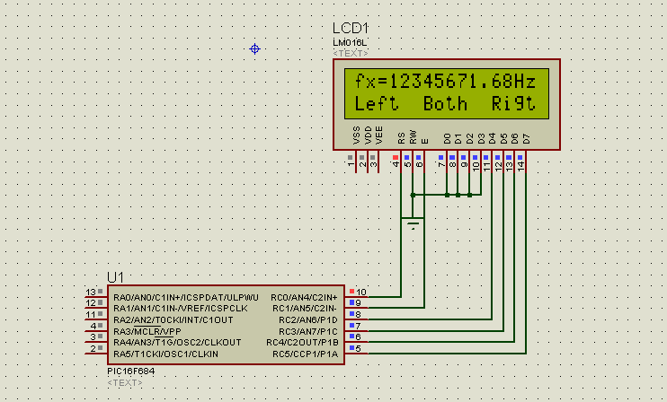
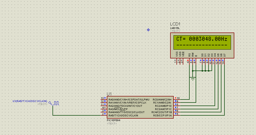
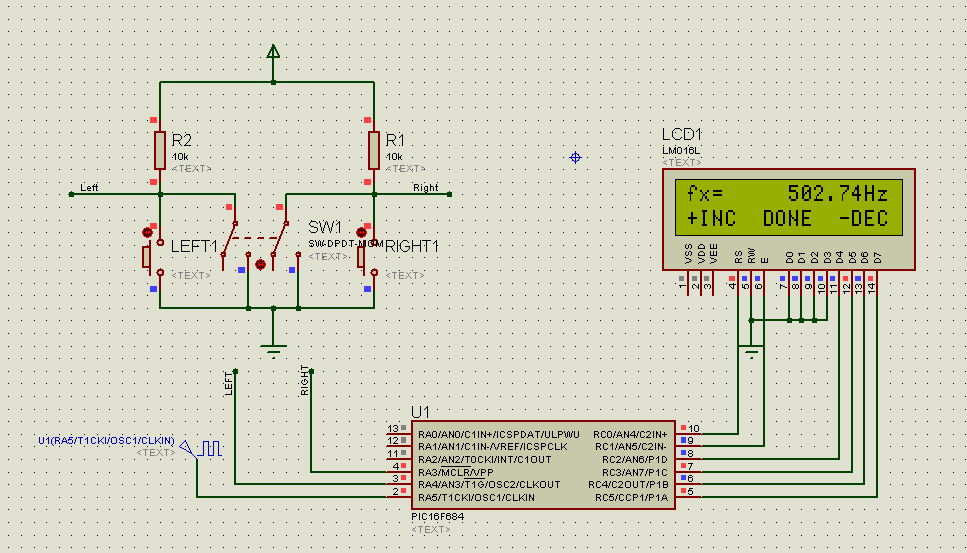
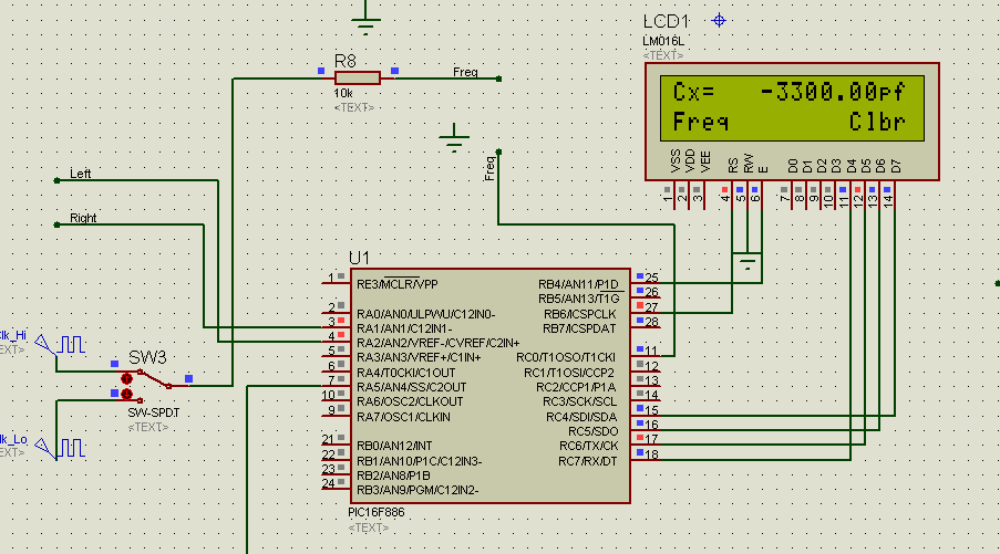
to measure L or C, we will need an oscillator whose output frequency depends on L and C.
that is the L/C tank circuitry you will see now.

(原文件名:mcu-based LC meter - 13 - f1.PNG)
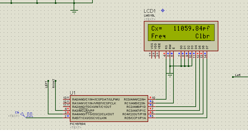
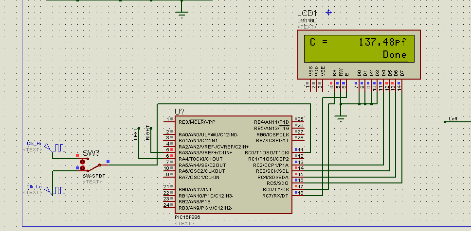
here, L1 (=L) is the inductor, and C3(=C) is the capacitor. The output frequency, f1 = 1/(2*pi*sqrt(L*C)), where pi=3.1415926.
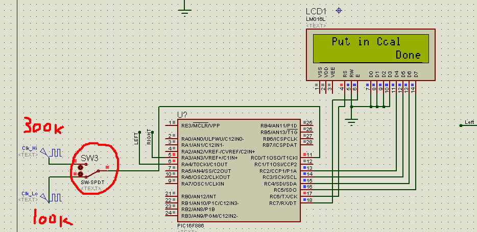
SW2 and C4/L2 simulate the calibration capacitor (Ccal), or inductor (Lx) or capacitor (Cx) to be tested.
the process goes like this:
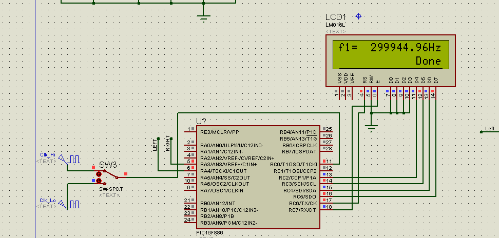
1) you run the oscillator without Cx or Lx in the circuit - SW2 is in the center. you get a frequency, call it f1:
f1=1/(2*pi*sqrt(L*C));
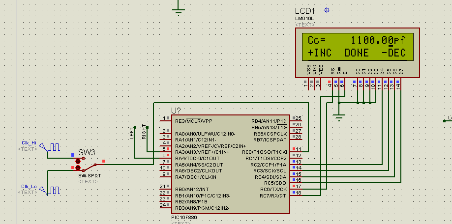
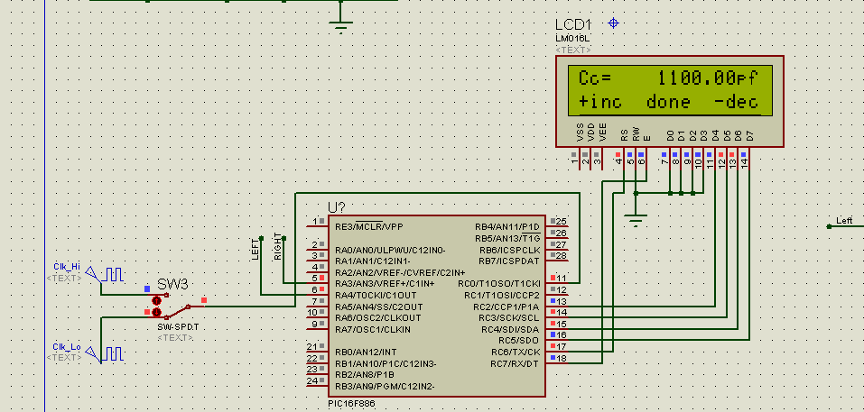
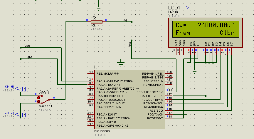
2) you then run the oscillator with Ccal in the circuit - SW2 is on the left. you get another frequency reading, call it f2:
f2=1/(2*pi*sqrt(L*(C+Ccal)));
obviously, f1/f2=sqrt(1+Ccal/C).
or C=Ccal/((f1/f2)^2-1).
from that, you get L.
that is, as long as you know Ccal, you can find out C, thus L.
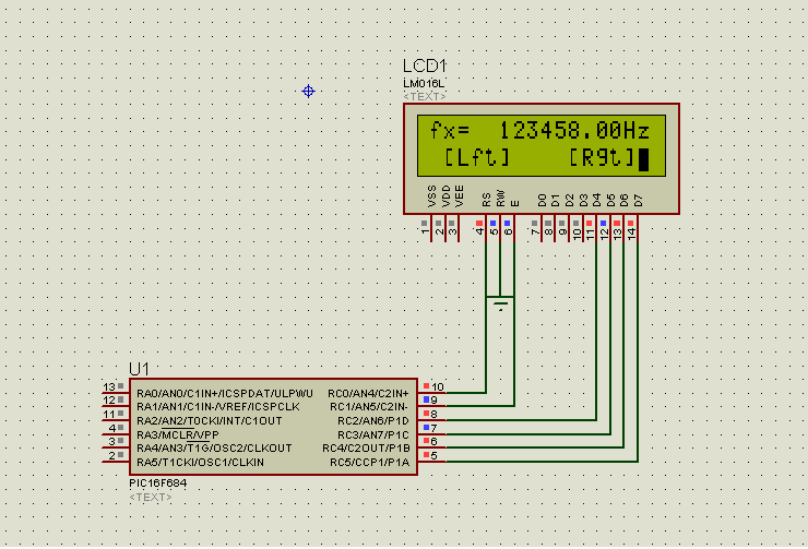
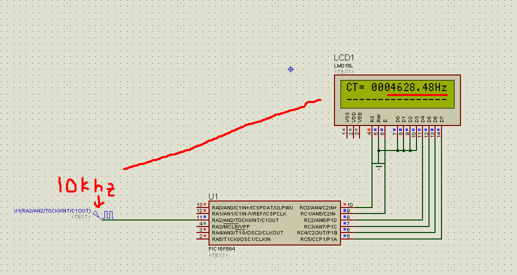
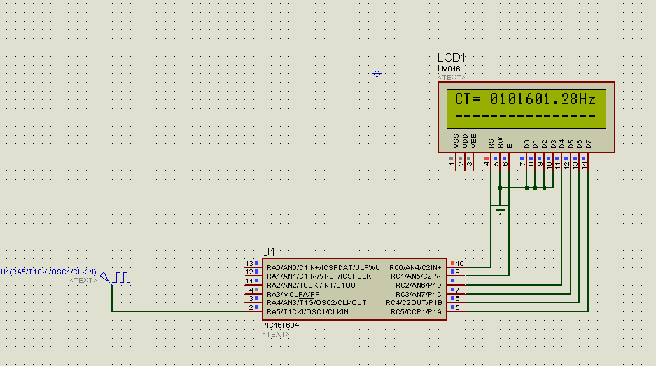
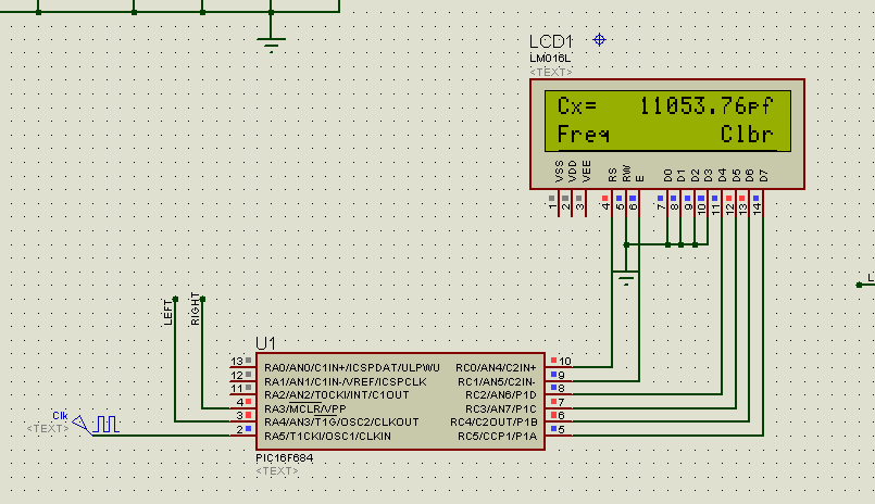
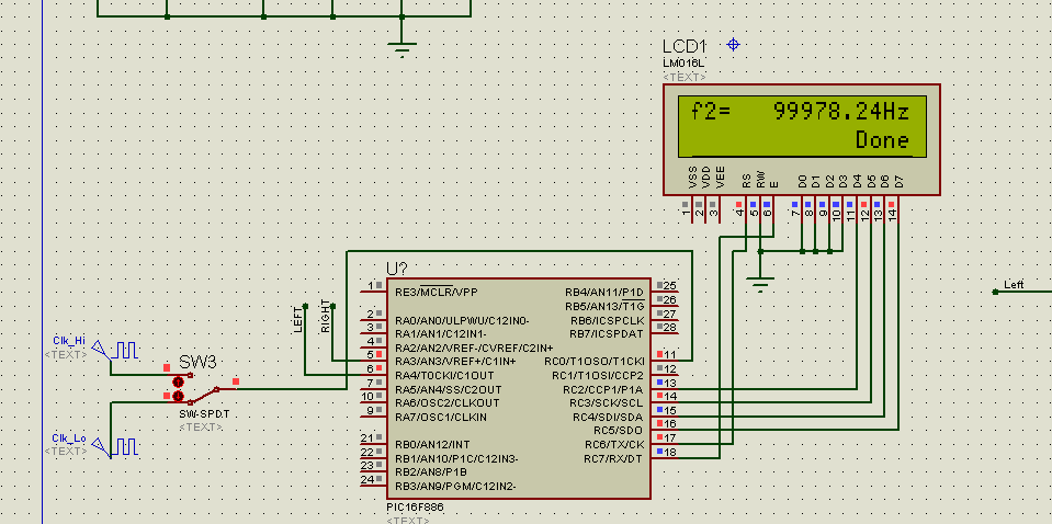
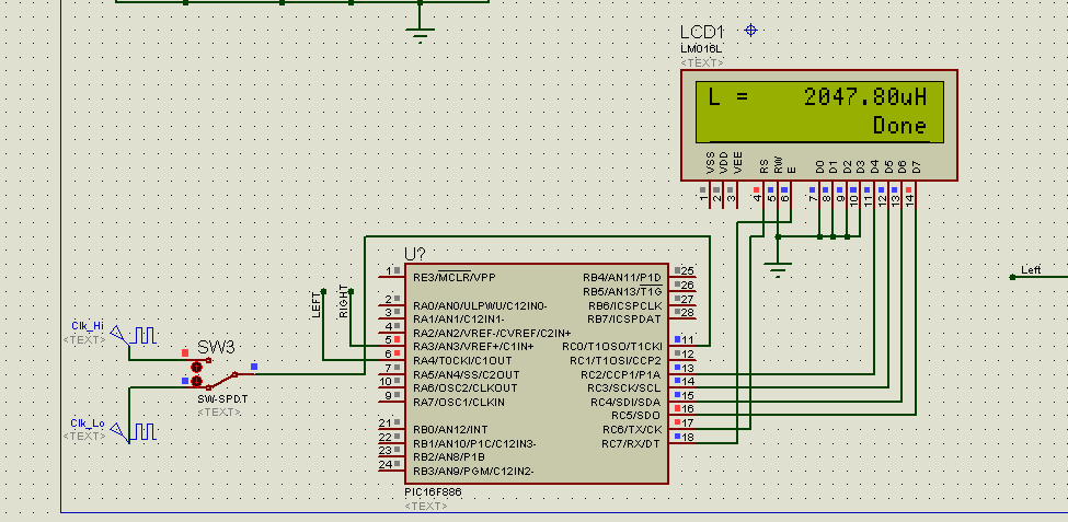
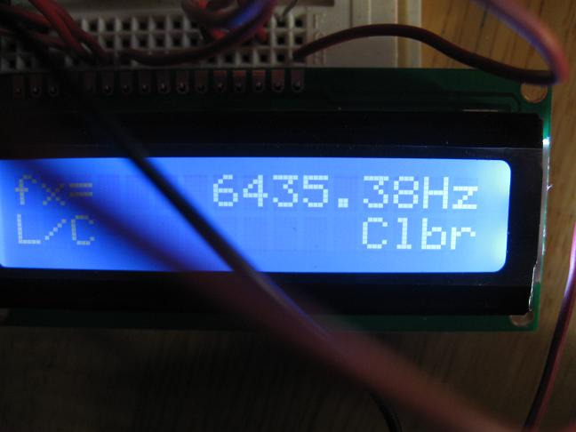
let's see the theory at work. the following is the same simulation run (uncaliberated frequency meter), after SW2 is pushed to the left (so Ccal=C4=1u).
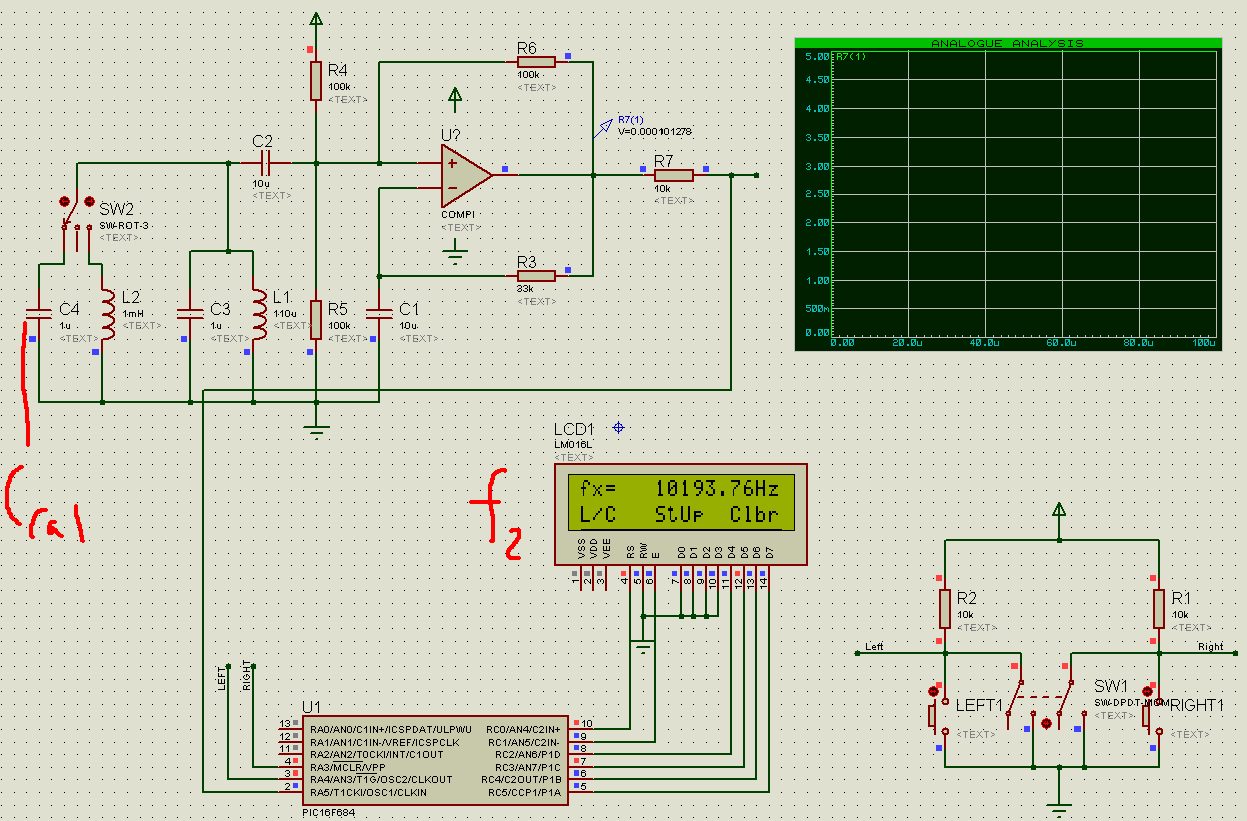
(原文件名:mcu-based LC meter - 13 - f2.PNG)
thus, we have f1=14525.76hz; f2=10193.76hz; Ccal=1uf. so C=1uf/((14525.76/10193.76)^2-1)=1uf/1.030527706=0.970376627, or an error of 3%, with a meter that is uncalibrated!
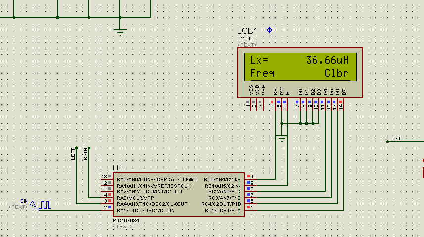
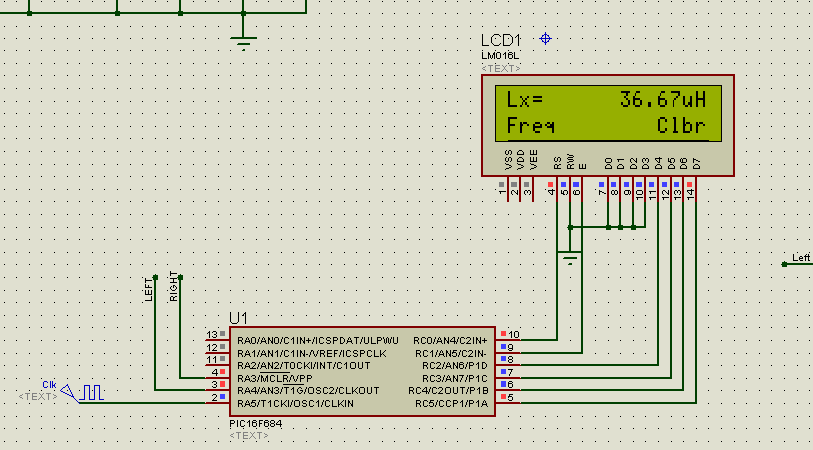
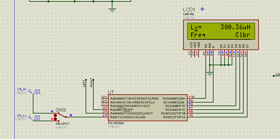
L=1/((2*pi*f1)^2*C)=123.715u. or a 10% error.
not great but not bad either.
here is the source files + .hex file.
点击此处下载 ourdev_491353.rar(文件大小:27K) (原文件名:16F684 - MyLCDDemo.rar) |
|


 发表于 2009-10-8 07:48:58