|
|
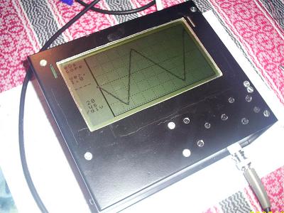
This project is amazing – how simple construction can be comparing to its power. I wouldn’t say that it is easy to build project, but average electronics hobbyist could do this as DSO circuit and PCB image are ready for manufacturing.
点击此处下载全部工程文件 ourdev_497262.zip(文件大小:169K) (原文件名:eoscope_develop.zip)
(原文件名:schematic_big.jpg)
点击此处下载电路图 ourdev_497265.rar(文件大小:658K) (原文件名:schematic_big.rar)
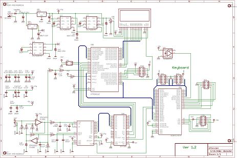
Oscilloscope samples signals at 40MSPS frequency which is much more than most powerful AVR microcontrollers can be clocked. For this there is 40MHz clock source used which is passed through programmable logic (XC9572 from Xilinx) IC. Analog signals are passed through OPA2652 operational amplifier and low-pass filter with 20MHz bandwidth. Then filtered signal enters ADS830 ADC chip which is clocked with 40MHz frequency. Converted signal then goes to AVR ATmega162 microcontroller. From where it goes to 240×128 (LMG6402PFLR with HD61830B controller) graphical LCD.
Features of AVR DSO (eOscope):
◦Maximum sample frequency: 40MSPS
◦Maximum input frequency: 5MHz
◦Maximum displayed frequency without aliasing: 10MHz
◦Input circuit bandwidth: 20MHz
◦Display resolution: 240×128 total, trace resolution 200×125
◦Sensitivity: 40mV/div
◦Coupling: DC
◦Input impedance: 10K
◦Power supply: single DC source 8V..10V, 1A
◦No incremental mode
◦Time base: 1s/div, 500ms/div, 200ms/div, 100ms/div, 50ms/div/, 20ms/div, 10ms/div, 5ms/div, 2ms/div, 1ms/div, 500us/div, 200us/div, 100us/div, 50us/div, 20us/div, 10us/div, 5us/div, 2us/div, 1us/div, 500ns/div
◦Trigger: digitally adjustable
◦Trace offset: digitally adjustable
(原文件名:AVR_DSO.jpg) |
|


 发表于 2009-10-29 13:33:01
 楼主
楼主
