|
|

楼主 |
发表于 2009-11-28 20:40:13
|
显示全部楼层
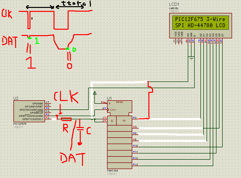
here is a short description of this 2-wire system.
most of the shift registers work by reading the SI / DAT line when the clock goes from low to high. so if you have a r/c network linking the clock to the SI, as in the attached schematic.
so when you transmit a short low pulse on the clock line, when you pull the clock line high, the voltage on the capacitor dips just a little bit, and the dataline will read a 1.
when you transmit a long pulse on the clock line, the voltage on the capacitor will have diped enough so the dataline reads 0 when the clock transits from low to high.
in my design, I sent the total pulse length (ttotal) to 60us. a short pulse would be 1 us. As to the long pulse, I want to give enough time so that the capacitor is fully charged up so I will pull the clock line low for no more than 50% of ttotal, aka 30us.
As to the value of the R/C network: I don't want to overload the mcu pins. to design for ARM chips which output 2ma, I want the current load to be 0.5ma. so I use R=3.3v/0.5ma=6.7k, and I will pick 10k.
the time constant of the rc network should not be too short so that a short pulse will still read a 1, but shortlyn't be too long either. I want to make sure that it gets to zero by 50% of the long pulse (30us). so 15us. that means a C of 1.5n, and I will use 1.1nf.
the program goes something like this:
void send_bit(unsigned char Ton) {
unsigned char Ttotal=60; //pulse cycle of 60us
SPI_CLK=0; //pull the spi_clk low;
delay_us(Ton); //delay;
SPI_CLK=1; //pull the spi_clk high;
delay_us(Ttotal-Ton);
}
so send_bit(1) will send a 1us low pulse on the clock line and shift a 1 into the shift register; send_bit(30) will send a 30us pulse on the clock line and shift a 0 into the shift registor.
obviously, this will take 60us*8=.5ms to send one byte.
you can easily implement the concept in my spi_send_byte(routine) without changing the rest of the program to create a two wire system.
(原文件名:12F675 2-wire 4bit.PNG) |
|


 发表于 2009-11-27 00:18:45


