|
|
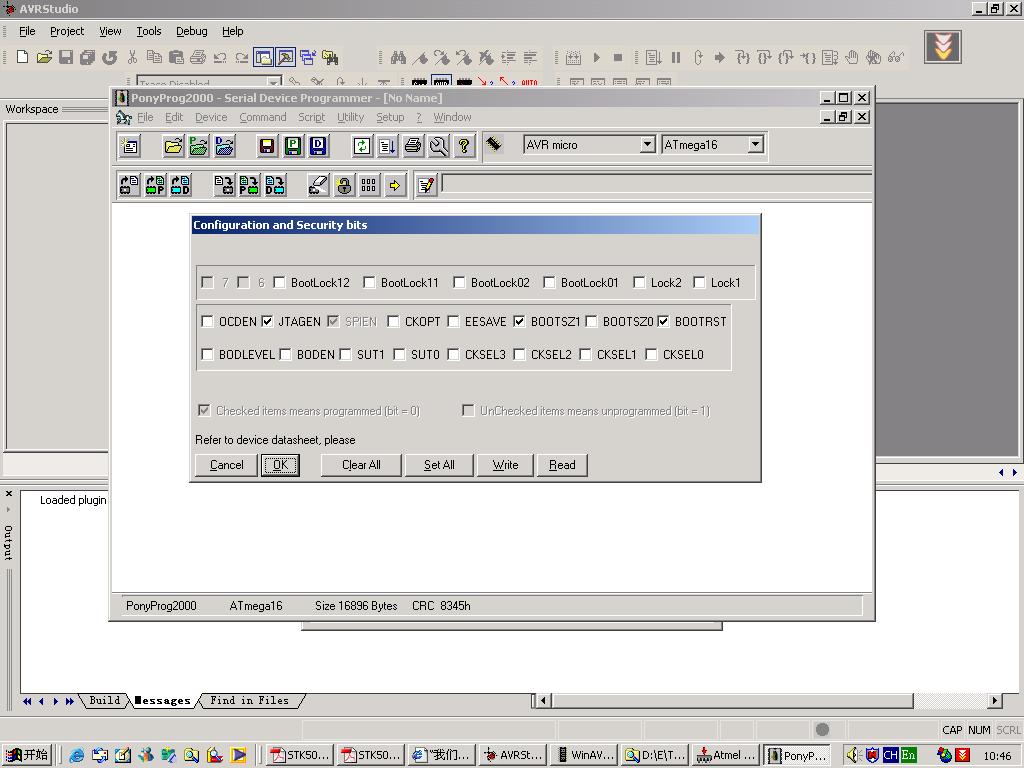
Mega16写入STK500v2 bootloader.hex,配置好熔丝位,写入M16以后都可以不用ISP编程(不再害怕熔丝位被改写不能应用ISP编程),是M16本身自编程,运行AVRstudio(STK500V or AVRISP),选择xxx.hex写入M16本身的Flash或EEPROM,写入之后M16直接跳到0X00000执行用户程序,非常方便好用,要编程按一RESET按键或断电源再接上电源,再次运行AVRstudio(STK500V or AVRISP)编程。
硬件:M16芯片、晶振 7.3728HMz RS-232接口 可参考M16 JTAG电路,用JTAG电路作实验。
熔丝位配置:
STK500v2 bootloader.hex
点击此处下载armok0156167.rar
M16/128TEST.C
PB3接LED闪动
#include <avr/io.h>
#define F_CPU 14745600 //M128
//#define F_CPU 7372800 //M16
#include <avr/delay.h>
#define FEQ 14.7456 //M128
//#define FEQ 7.373 //M16
#define BIT0_POS (1<<0)
#define BIT1_POS (1<<1)
#define BIT2_POS (1<<2)
#define BIT3_POS (1<<3)
#define BIT4_POS (1<<4)
#define BIT5_POS (1<<5)
#define BIT6_POS (1<<6)
#define BIT7_POS (1<<7)
#define BIT0_NEG ((unsigned char)(~(1<<0)))
#define BIT1_NEG ((unsigned char)(~(1<<1)))
#define BIT2_NEG ((unsigned char)(~(1<<2)))
#define BIT3_NEG ((unsigned char)(~(1<<3)))
#define BIT4_NEG ((unsigned char)(~(1<<4)))
#define BIT5_NEG ((unsigned char)(~(1<<5)))
#define BIT6_NEG ((unsigned char)(~(1<<6)))
#define BIT7_NEG ((unsigned char)(~(1<<7)))
#define LED_RED_ON PORTG|=BIT0_POS
#define LED_RED_OFF PORTG&=BIT0_NEG
#define LED_RED_TOG PORTG^=BIT0_POS
//#define LED_RED_ON PORTB|=BIT3_POS
//#define LED_RED_OFF PORTB&=BIT3_NEG
//#define LED_RED_TOG PORTB^=BIT3_POS
#define LED_GREEN_ON PORTB|=BIT0_POS
#define LED_GREEN_OFF PORTB&=BIT0_NEG
#define LED_GREEN_TOG PORTB^=BIT0_POS
void delay_1ms(void) ;
void delay_nms(unsigned int n);
int main(void)
{
DDRG = (1<<0); //PORTG_0 LED_RED //M128
DDRB = (1<<3); //PORTB_3 LED_RED //M16
//*************************************************
while(1)
{
unsigned int i=0;
for(i=0;i<100;i++)
{
delay_nms(100);
LED_RED_TOG;
LED_GREEN_TOG;
}
}//while(1)
return 0;
}//main END
//******************************
void delay_1ms(void) //1ms延时函数
{
_delay_loop_2(FEQ*250-2);
}
//******************************
void delay_nms(unsigned int n) //N ms延时函数
{
unsigned int i;
for (i=0;i<n;i++)
delay_1ms();
}
-----此内容被andy于2005-07-14,11:32:45编辑过 |
|


 发表于 2005-7-14 11:18:26
 楼主
楼主