|
|

楼主 |
发表于 2011-8-13 00:11:30
|
显示全部楼层
回复【6楼】1ongquan
-----------------------------------------------------------------------
没仿真,ads中找不到bb135所以....而且ads中我仿不来VCO
谁能指导下??
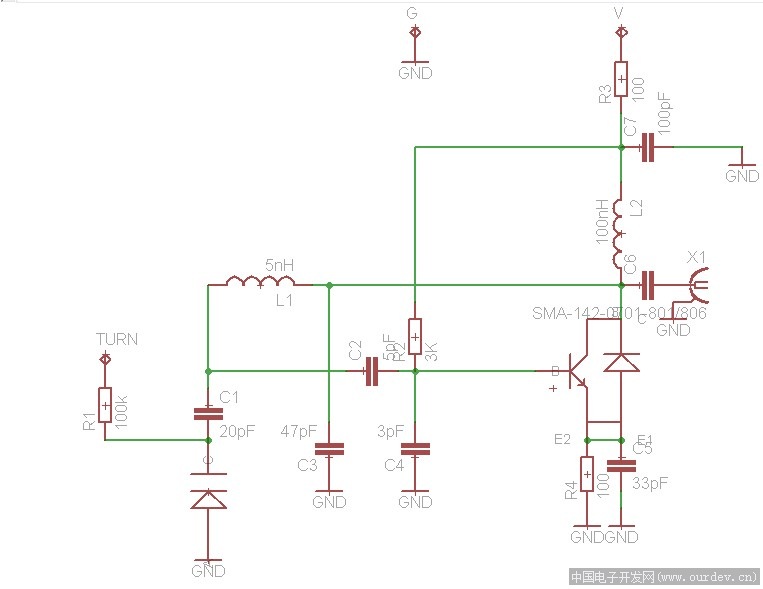
电路来自于:
http://www.qsl.net/va3iul/High_Frequency_VCO_Design_and_Schematics/High_Frequency_VCO_design_and_schematics.pdf
The Vackar VCO circuit incorporates a π-section tank to attain the needed 180° phase-reversal in the
feedback loop.
· However, the inverted feedback signal is not directly fed back to the input of the active device; rather,
it is loosely coupled through a small capacitor. Often, a shunt capacitor is introduced to further
reduce the coupling.
· The basic idea is to isolate the resonant circuit as much as possible from the input of the active
device, consistent with obtaining reliable oscillation.
· This circuit is particularly advantageous with solid-state devices, and especially with bipolar
transistors that have inordinately-low input impedances and that present a widely-varying reactance
to the tuned circuit as a consequence of temperature and voltage changes.
· Once the overall circuit is operational, the values of capacitance C1 in series with Cvar and collector
capacitance (C2) may be optimized for best stability. Generally, it will be found that the capacitor
closest to the collector of the transistor can be several times larger than the capacitor associated with
the base circuit.
· The introduction of attenuation in the feedback loop (via the small capacitor in the Vackar) prevents
over-excitation and effectively isolates the resonant circuit from the active device.
· The frequency tuning range of Vackar VCO is above one octave, not observable to many oscillator
types.
· The frequency tuning is provided independently of the coupling to the LC tank circuit.
· The parametric variables of the transistor (which depends by the bias current and temperature), are
isolated from the resonator.
· The transistor input is not overloaded as other VCO circuits and the collector output has low
impedance providing low gain just to maintain the oscillation.
· The feedback division ratio is fixed (typical range for coupling ratio is 1:4 up to 1:9). Even if the VCO
is tuned, the impedance divider is fixed, in this way increasing the stability.
· Two negative sides of Vackar VCO are the critical starting oscillation point, and the low output level,
which always requires using a buffer amplifier. When the oscillation doesn’t start means that it |
|


 发表于 2011-8-12 18:49:15