|
|
http://www.aplomb.nl/TechStuff/Dragon/Dragon.html
New design with 74HC244 / September 18, 2007 Go
AHT-chip identified / September 20, 2007 Go
My Dragon
From Atmel's site:
The AVR Dragon sets a new standard for low cost development tools.
AVR Dragon supports all programming modes for the AVR device family.
It also includes complete emulation support for devices with 32kB or less Flash memory.
Programming Interfaces
- In-System Programming
- High Voltage Serial Programming
- Parallel Programming
- JTAG Programming
Emulation Interfaces
- JTAG
- debugWIRE
The AVR Dragon is USB powered and is capable of sourcing an external target.
A prototype area allows simple programming and debugging.
The AVR Studio online-help contains a complete list of supported devices.
I purchased one of these (thanks Sebastian, for helping me out) because it has so many features. See the quote above.
But soon became clear that this device was vulnerable:
On AVRFreaks.net several users reported "dead" Dragons. Or should I say "slayed Dragons" ??
Three main reasons:
1. The Dragon is USB-powered, and has a step-up converter on board to generate 12V for the HV-programming.
However, when touching the area where this circuit located (down-left corener on the picture), causes the voltage to go up, and that's fatal. Dragon DEAD.
2. Powering the Dragon from a USB-port that is not "prepared" to deliver the 850 mA rush-in current, causes the step-up coverter to die, because of the sudden drop of the USB-supply voltage.
3. If the Dragon is connected to a faulty board (sh*t happens ...), it's interface isn't rugged enough to withstand that abuse.
Since we know this, .... time for some action.
1. Solution is simple: don't touch the Dragon in that area. And how to accomplish that ? Give it a proper housing.
2. Not all PC-USB-ports can deliver the rush-in current, and failing to do so means ..... ah, we know that now.
Solution: Power the Dragon from an USB-hub with an external, beefy power-supply.
3. Add a buffer that can withstand that abuse.
A close-up of the 2 chips that take care of the Dragon-to-target /Reset-line:
At Freaks we're trying to find out what chips these two are: the AHT-print does reveal enough. And the Dragon-schematic is not public. If more information is available, I'll post it here.
News: fellow-freak ttyridal found out that it's a NLAS2066USG from ON-Semiconductor
KKP, another fellow-freak, did quite some research on the Dragon's fragility, and designed (and built) the Dragonhide:
http://n1.taur.dk/permanent/dragonhide.pdf
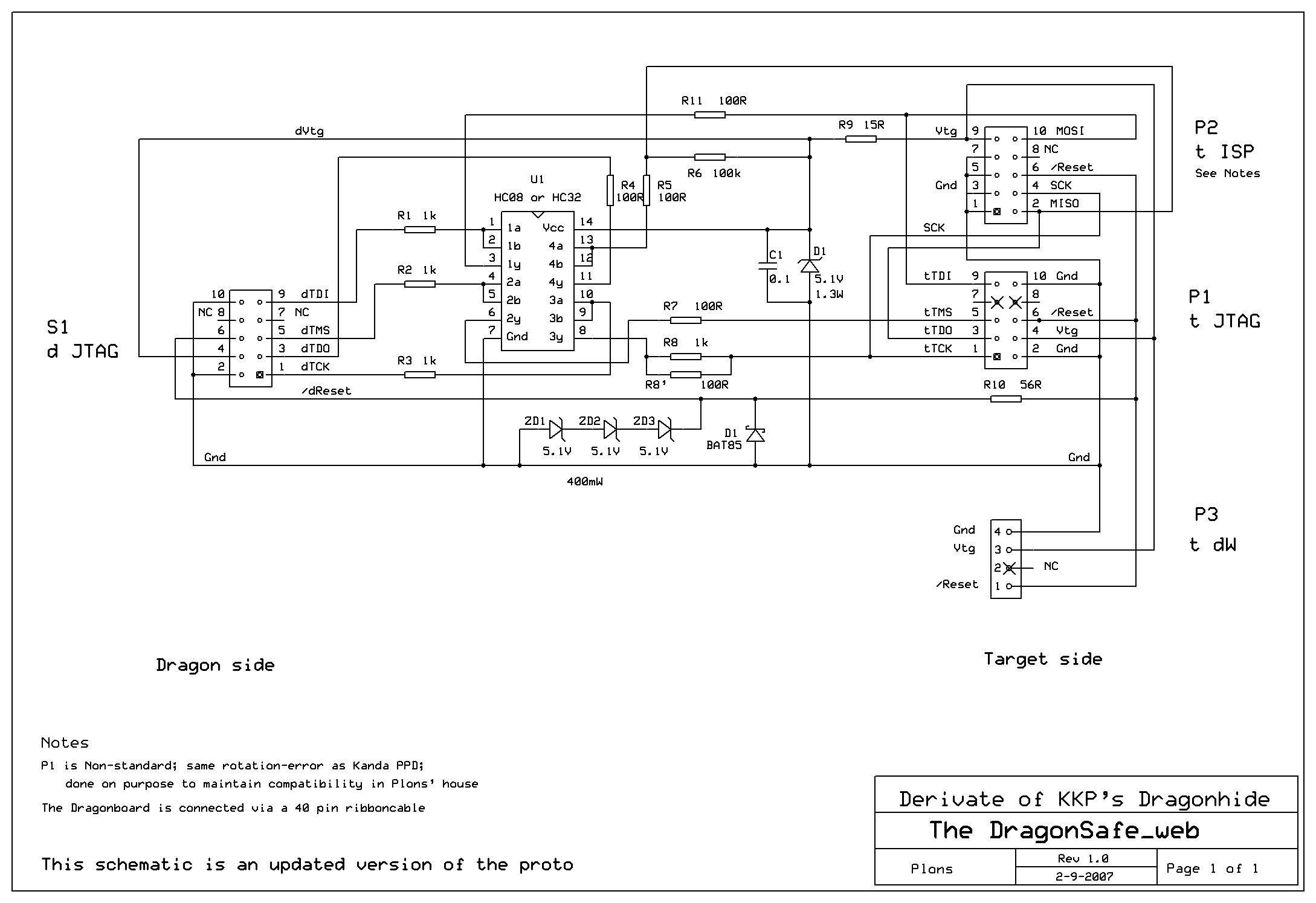
I adapted his design to create my own interface&protection board.
Since my demands are less than KKP's, I used a plain 74HC08 (or HC32 if that suits you better) for the buffering, and didn't create a Pod-board.
The first build:
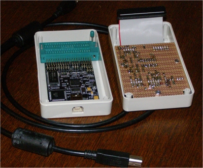
The box in which the Dragon is shipped (it's lair :-), was modified to allow for the ZIF-socket and the USB-plug.
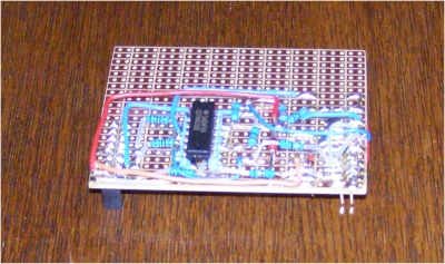
Since I used a single sided protoboard, and didn't want the connectors to "pull" the copper-clads, the connectors were placed on the component-side, and most of the circuitry on the copper-side.
Result:
Okay ...... better than a bare Dragon, but not very good looking ..... watch ....
JTAG connector and ISP connector ......
It worked perfectly fine, but didn't look very nice
So I decided to build a proper lair for my o so fragile Dragon.
The self-tapping screws in the ZIF-socket were removed, and replaced with M2 bolts and nuts.
Btw, sounds odd, "bolts and nuts" for such small hardware ......
At the USB-side, two strips of dual-sided adhesive foam stick the board to the bottom.
The new built interface is much nicer than the proto one, but unfortunately I forgot to take a picture of the componentside. Two M2.5 and one M3 keep the interface in place.
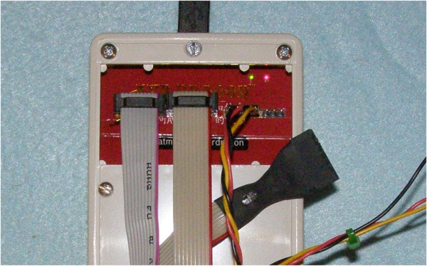
The 40-pole ribbon-cable (modified IDE cable) connects to the row of connectors on the Dragon for JTAG, ISP and HV-programming. The JTAG connector has all the signals that are needed for this purpose. And in the (rare) case that I need HV-programming, all that's needed is removing the 4 screws of the housing. I am using AVR's now for 2 years, and upto now, I never needed HighVoltage programming. But it's nice to have, just in case ......
From the carton of this beast, I cut an inlay. For the status-led's on the Dragon-board, I had to find a solution: plastic fiber :-)
The visible ends of the fiber (1mm diameter) were carefully touched against the soldering-iron. The top gets a mushroom-shape, and that's great: they will not slide into the lair. To prevent them from falling OUT .... some poster-gummy on the PCB holds them.
Btw, I am famous for my poster-gummy use ;-)
The left connector is JTAG, the second ISP and the third debugWire. The fourth was intended to be used for jumper-selectable power from the Dragon to the Target ...... but I decided not to implement it: it would make the Dragon more vulnerable again.
The result:
Nice huh ? That's why I stored the pictures, schematic etc. in a folder MyDragon_NICE ....
And NICE can also be read as Nard's In Circuit Emulator ;-)
( Technically spoken, the Dragon is not an ICE like in the good old days, for the 68000 Motorola and 80xx Intel. But it comes close, and for �50 it's a great tool)
--------------------------------------------------------------------------------
Leftclick on schematic to enlarge / or rightclick and choose Save as
The schematic is drawn with ExpressSch. You can download it from http://www.expresspcb.com/
The .sch-file of my Dragonlair can be found here
TIPS:
If you plan to build your own: Use a 74HC244 instead of the 74HC08 or 32.
The 74HC244 is a busdriver and therefor more powerfull and can withstand heavier abuse ;-)
I should have realized that earlier.
Or: go for the original Dragonhide-design at http://n1.taur.dk/permanent/dragonhide.pdf
JTAG-ing over several meters ..... sounds like fun ...
--------------------------------------------------------------------------------
Credits and Notes:
The background picture of this page is copied from AVRfreaks.net
The Picture from the bare Dragon (at the top of this page) comes from the Atmel's site
Great thanks to Kasper (KKP) for his excellent work
Thanks to ExpressPCB.com for their nice program
All rights reserved.
Update:
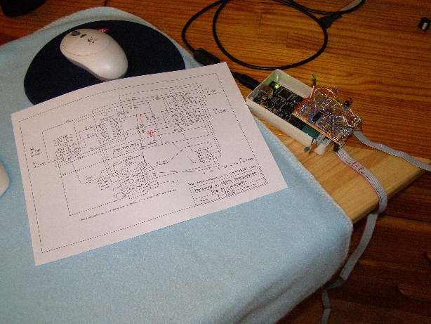
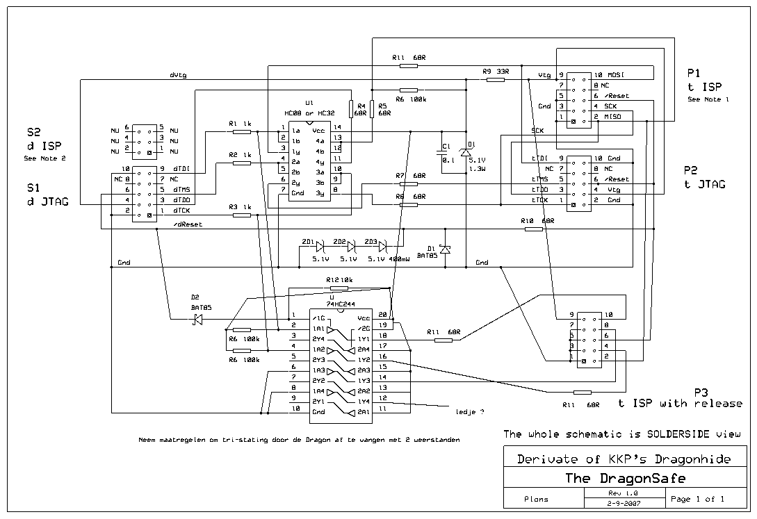
Okay, I did quite some testing with the new Dragon-safe. And found that the buffer does its job. But it does not release the ISP-lines when done: if the application uses these lines, there is a conflict (of interest ;). So I modified the proto and created a second ISP-connector of which the signals are buffered with a 74HC244. The /Reset-line from the Dragon acts as /Enable for this buffer. It was a bit uncertain if it would work fine .... therefor the modified proto. Quite a mess, if I may say so ....
To make it easier for myself to distinguish between existing components and interconnects, I used non-rectangular lines: and I must say that it works !
A more detailed mess: the pencil prevents stress on the extended 10-pole JTAG-connector.
Just for a smile, here the schematic of this test-rig:
The 10k-pull-up on pin 1 of the 74HC244 in combination with the 10k pull-up I generally use on target-boards, was too much load for debugWire (dW) functionality. So I needed to do something on that.
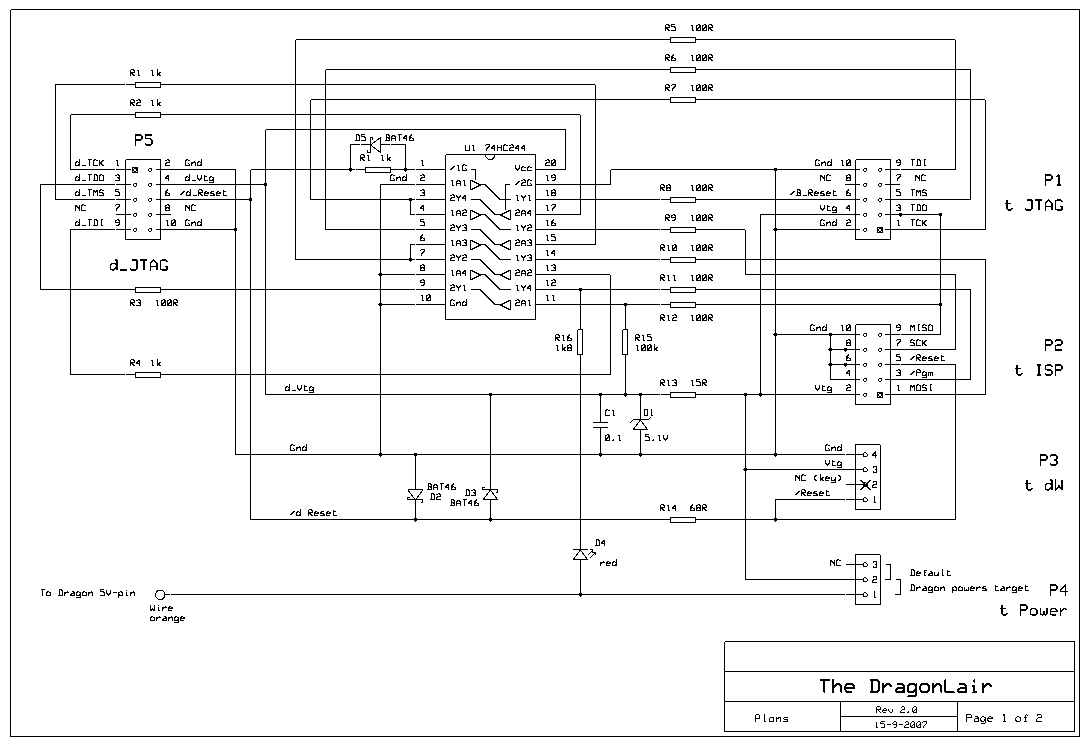
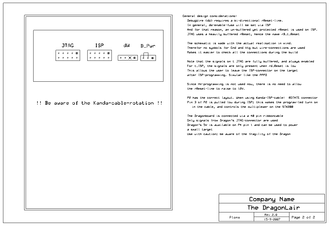
There were several other considerations .... you can find them on sheet 2 of the new schematic.
Leftclick on schematic to view or download the 200dpi .png
Sheet 1
Sheet 2
The schematics are drawn again with ExpressSch. You can download it from http://www.expresspcb.com/
The updated .sch-file of the DragonLair rev 2.0 can be found here
As you can see, this time the 5V-Dragon-power is available on connector P4. But use it with care.
I also added a LED to show ISP-activity. When you connect your target-board, this LED lights up. When you power the target, and this LED stays on, you connected the ISP-plug the wrong way around. F.i., a Kanda cable ;-) Because of the buffering, nothing dies (yes, I tested that)
The buffer between Dragon and the JTAG-lines on P1 is always enabled. The reset-line comes from the buffer, and not from the Dragon itself. This mechanism could have been applied to ISP as well, and yes, .... that was the preferred way.
BUT: there is a good reason for NOT doing so. It has to do with dW. dW needs a bi-directional /Reset-line. And to start dW, we need ISP to set the dW-fuse. After that action, ISP is crippled, as the /Reset-line of the target-board is in use for dW . To re-enable ISP, you need to do that in a debug-session. (see Help-file AVR-Studio). To prevent that you, as user, need to keep on swapping cables, the current-limited and clamped /d_Reset is on the ISP-conector. Like on the dW-connector. So you can use dW with the ISP-cable. But if your target-software uses the ISP-lines, disconnect the ISP-cable, and attach the dW-cable.
This is my dW-cable. As you can see it has 2 connectors on the end: a 10-pole Kanda-ISP, and a 7 pole Plons-ISP. And since I'm now showing off: the 7 pole-ISP-Single-In-Line is defined with the AVR-pinning in mind. For an ATtiny2313 f.i., it's easy to route on a PCB. And as a second note: key-ing of these connectors is IMSO*) a necessity: think of Murphy. Key-ing locks Murphy out.
If you don't use dW, you can replace /Reset on pin5 of P2 with /B_Reset (is on P1). That makes the Lair even tougher.
(Btw, not using dW would be a pitty .... it's a wonderfull tool)
Maybe you noticed it already .... but in case not: the zeners are no longer on the /d_Reset. My guess is that Kasper (KKP) added these to allow HV-programming. Since HV-programming should be done without any of the cables as shown here connected, I took them out, and clamped /Reset against the 5.1V zener.
There are some more interesting notes on page 2 of the schematic.
Take f.i. nr. 2: why did I draw the schematic as I did ? Watch ....
I took it from the bin indeed ....
*) IMSO: In My not humble but Strong Opinion |
|


 发表于 2007-11-5 12:12:02
 楼主
楼主